

I built the Far Reach to be simple—and she has served me very well that way. She has never failed me and in our time together she has safely carried me to a number of magical destinations. With her taller rig, longer bowsprit, and modified underbody she has proven to be surprisingly capable upwind as well as off the wind. She is fast. In fact, I have had to slow her down a number of times, especially singlehanding. She is as reliable as the day is long. She is comfortable. She is beautiful. As John Keats the poet observed, “A thing of beauty is a joy forever.”
I loved my two offshore voyages to the Virgin Islands and back to North Carolina. I am ready to go back….and I will…. But first, there are a few projects I added to the list that need to be completed this year. One project is to add a robust rub-rail to protect the topside of the boat. I saved the 70′ of 3/4″ half oval bronze rail original to the Far Reach knowing at some point I would add the kind of tough rub-rail to properly protect her. So, I have begun planning for that project which I will tackle in the spring of 2020.

But, there is a much bigger project with significant implication for both the Far Reach and for me. This past summer, I came to the conclusion that I was ready to install an inboard diesel engine….
Installing an inboard engine was not a decision made lightly. I have loved the challenge of maneuvering the Far Reach under sail during more than 8,500 nautical miles of sailing. The sense of accomplishment from sailing the boat in all matter of conditions and in all kinds of places is immensely rewarding. I have also enjoyed sculling her when conditions permitted—a bit of a lost art I might add. So what has changed?
There are three main reasons that drove the decision to install an engine:
First, there are a surprising number of boaters that display a serious lack of basic knowledge on the water that create risk for a heavy displacement boat operating under sail in confined areas. I have come to the conclusion that many skippers simply don’t pay attention to what is going on around them when they are operating under power. It’s not just powerboats, it’s any kind of boat. These skippers are “driving” their boats as if there are behind the wheel of a car. They are often inattentive (and I am being polite here) and will block you into a situation when even though you have the right of way there is simply no way to execute the intended maneuver without risk of collision. The result is there are places I would like to sail but I find myself choosing not too because I don’t trust the skill sets of other boaters….
Second, there are an increasing number of places that I would like visit on the Far Reach (some skinny rivers come to mind) that simply can’t be reasonably explored singlehanded under sail.
And, last, while the outboard bracket has been marvelously effective it is a distraction from the beautiful lines of the boat that give me such pleasure.
I want to make a point and state at no time have I felt not having an engine was a safety issue with regards to maneuvering the boat. I have always felt totally in control of the Far Reach whether beating up a narrow channel, tacking through a crowded mooring field, or sculling into or out of a slip. I do not view an engine as a safety device or safety equipment. Equipment does not keep you safe. What’s between your ears keeps you safe. By that, I mean experience, judgment, and decision-making.
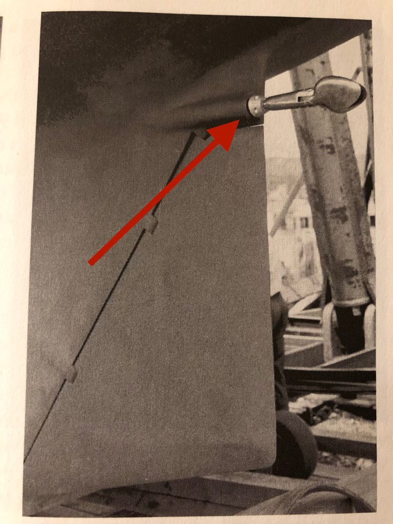
From the very beginning of the our boat build, we always believed we would install an inboard engine at some point. In fact, when I designed and installed the interior I had an idea about what a potential installation might look like and thus left room for the possibility. For more info on the the decision to sail without an engine click on link below. There you can read through an early post from 2014 during the boat rebuild to gain insight into my thinking at that time. http://www.farreachvoyages.com/projects/scullingdinghyoars.html
Once I came to the conclusion that I was ready to pursue the installation of an inboard engine I began working out design options that would retain as much of the Far Reach’s sailing performance as possible. I considered everything from an inboard electric drive to a modified Torqeedo Sail Drive, to a traditional inboard with an associated propeller located in an aperture with a feathering propeller. In the end, I decided to go with the plan I had originally considered many years ago—an offset propeller shaft and folding propeller along the lines of that championed by the legendary Hal Roth on his famous highly modified Spencer 35 Whisper.
Roth’s design essentially relocated the propeller shaft slightly above the top of the rudder and alongside the rudder post. This approach positions the propeller immediately aft of the trailing edge of the rudder allowing the use of a folding prop. A folding prop produces the least possible drag for an inboard engine.
I discussed this approach with Tim Lackey who has been an invaluable mentor to me for over a decade and is highly experienced in all things sailboat related. We discussed the pros and cons over a number of weeks with sketches and photos and a considerable analysis of how it might work and what to look out for in an effort to ensure the best possible result. If it works, as I believe it will, Tim’s thoughtful guidance will have been essential. If it does not work, then the fault will be entirely my own as a result of my own stubbornness and silly flights of fancy.
One of the limitations of the Roth design as it pertains to the Far Reach is the propeller will not be in as deep water as would be the case were I to cut open the original aperture and reinstall the shaft/propeller there. The original location ensured the propeller would remain fully submerged at all times. A propeller too close to the surface will have a tendency to ventilate (suck air down from the surface) thus losing thrust and in a big swell if the boat experienced severe pitching the prop could come out of the water causing the propeller to cavitate. Another limitation is with the propeller located behind the rudder the reverse performance will be degraded. The ability to stop the boat will probably remain unaffected but reverse steering control under power will be compromised. How much loss of control is unknown. But, I reasoned that the vast majority of time an engine is used to propel a boat forward and not backward. I chose not to compromise the significant performance gains of using a two blade folding propeller without an aperture under sail in order to enhance steering control in reverse.
The decision to install an engine was difficult. I wavered back and forth for months and even now, I am not convinced it is the right thing to do. When I built the Far Reach I had a very specific vision to fulfill a very specific need. I was searching for a path to a spiritual experience. I would say in so many ways she has provided that for me. The experience is hard to describe. The reality is I lack the words or the skill with the words to explain the journey or the magic. But, when the magic happens it is tangibly real. The gist is, for me, the simpler the boat the less there is to get between me and the magic. And I need to be careful moving forward that I don’t create barriers or obstacles that limit the magic or even prevent it from occurring at all. To help me sort out the decision to add an engine I came up with the following questions:
1. Will adding an engine enhance my sailing experience or detract from it? If so, how?
2. Will adding an engine support me doing things I might not otherwise do and is that a positive thing?
3. Will adding an engine make the boat more capable or less capable?
4. Am I prepared to do the work?
5. If I install an engine can I do it in a practical professional manner that is clever, thoughtful, simple, reliable, effective and eliminate the loss of sailing performance that occurs when a long keeled boat has an engine?
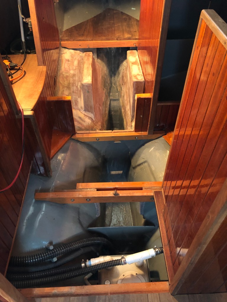
I spent time drawing the plan out. I measured the space under the cockpit and bridge-deck that would have to accommodate the engine. I made mock ups of the propeller shaft and folding propeller and drew more lines. I discussed propeller options with Flex O Fold in Denmark. I visited with Beta Marine in Oriental NC a couple times. I downloaded engine drawings and made a template for the engine footprint.

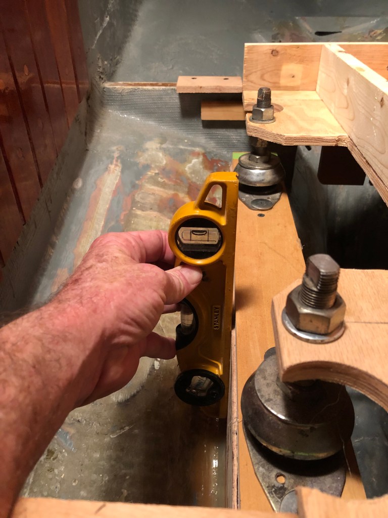
There were several important considerations. I needed to get the propeller deep enough into the water to work effectively. But, the deeper I put the propeller into the water the further forward the engine was going to be positioned in the boat. I also I had to make sure the propeller shaft would miss the rudder post enough but not be so far offset it would effect the steering of the boat under power.

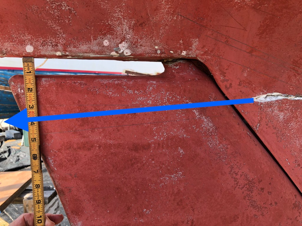
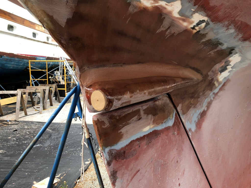
The only way I could get the propeller deep enough in the water to be effective was to cut the top of the rudder off so the propeller shaft could be properly positioned. There was some educated guess work here. I wanted the propeller shaft to be as close to horizontal as possible to increase thrust under power and reduce drag under sail. I settled for 5 degree down angle with the knowledge the original diesel was installed at 15 degrees down angle. I thought for a long time about how to cut the top of the rudder off and fill that void. Finally, it occurred to me I could epoxy the part I cut off to the underside of the hull immediately above the rudder. Then, I could build molds to create a solid epoxy fairing to bridge the gap between the new hull extension around the exposed rudder post and onto the hull. The best part is I thought I could do all this without dropping the rudder which is a complex and time consuming evolution. As mentioned previously I spent considerable time thinking about the project visualizing it from start to finish. I made countless drawings. I measured and calculated over and over. I shared my thinking with trusted friends.

Part of the planing required me to decided how to address the shaft-log itself. I decided to go with a 1.5” ID x 1.75” OD tube made of G10 epoxy. I married that to a 1” ID x 1.5” OD x 4” long Johnson shaft bearing. The shaft bearing fits inside the end of the shaft log. The 1” ID accommodates the planned 1” diameter propeller shaft. I also decided to go with a standard stuffing box vice a dripless seal. I wanted something I could repair in a distant location or repair at sea if the seal failed. Tim Lackey, as always the zen master, help me understand what I needed and how the parts worked.

I used a G10 tube, stuffing box, and Johnson bearing.
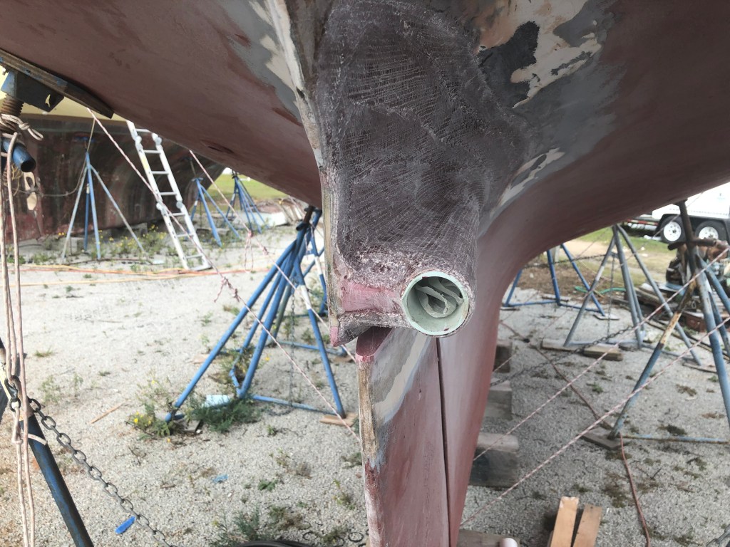
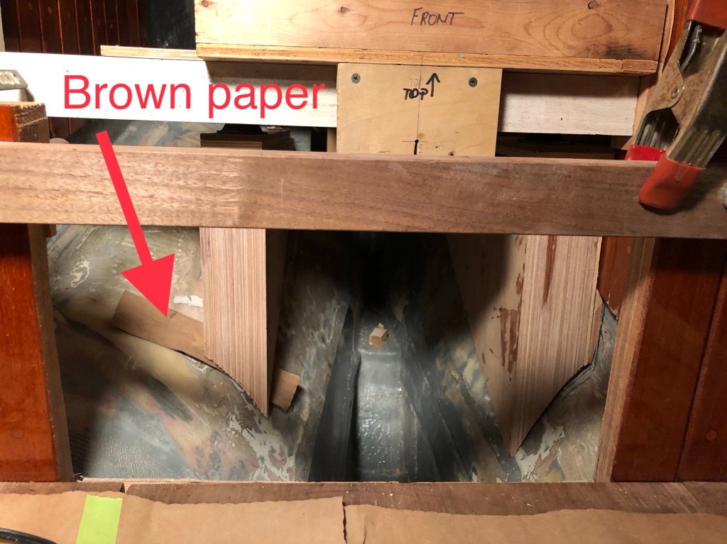
I decided where I thought the shaft log would need to be installed to support the propeller shaft and I drilled an exploratory hole.
Then, I chased the hole with a very long 1/4” bit installed in a 2.25” hole saw and cut a hole through the hull and into the engine compartment. The large diameter hole saw allowed some wiggle room to best position the shaft log.
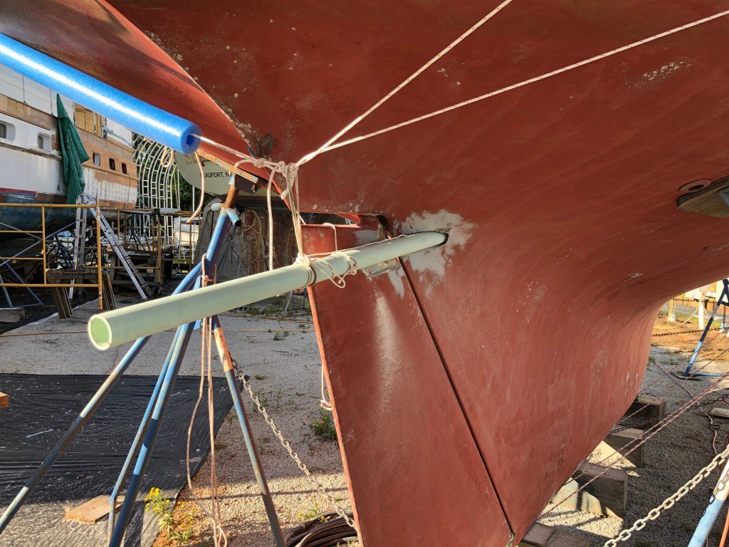
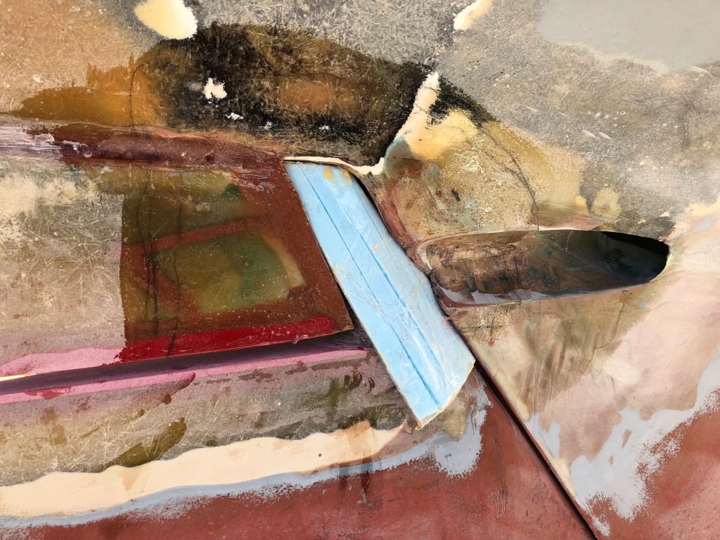
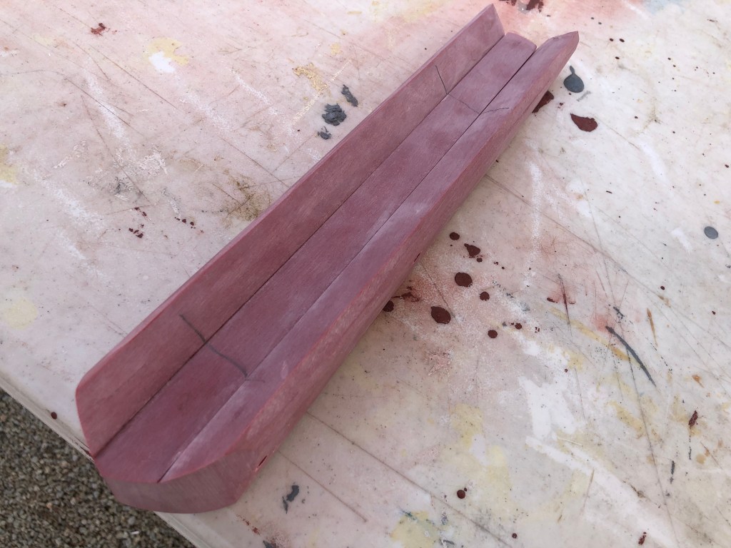
I test fit the shaft long and and made more measurements and thought about it for a day or so. I drew lines on the rudder and cut 5” off the top of the rudder with a saws-all. I was now fully committed.
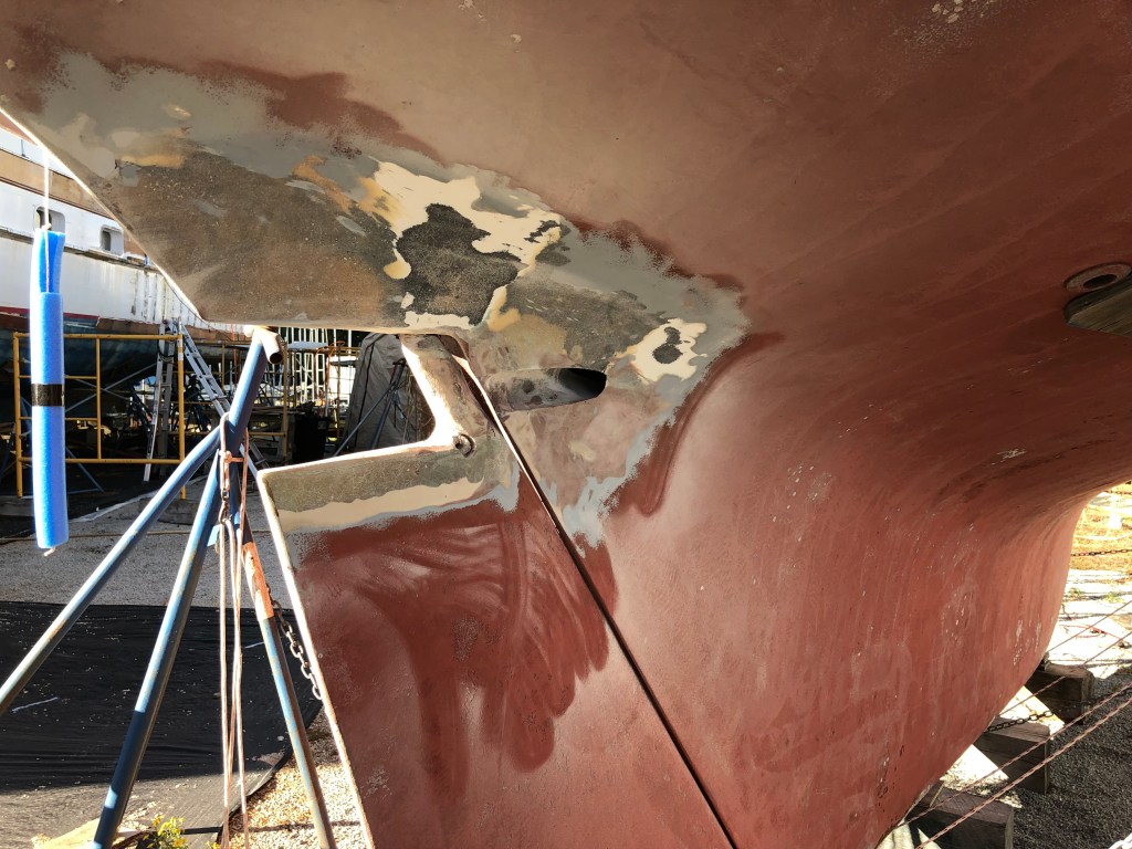
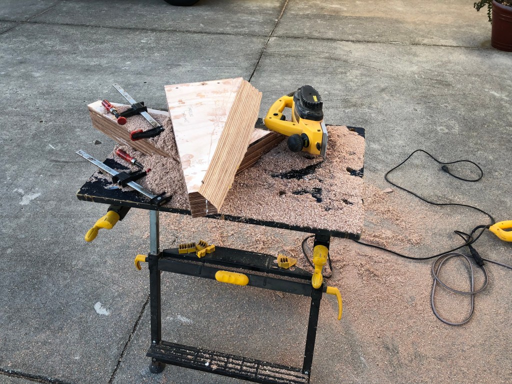
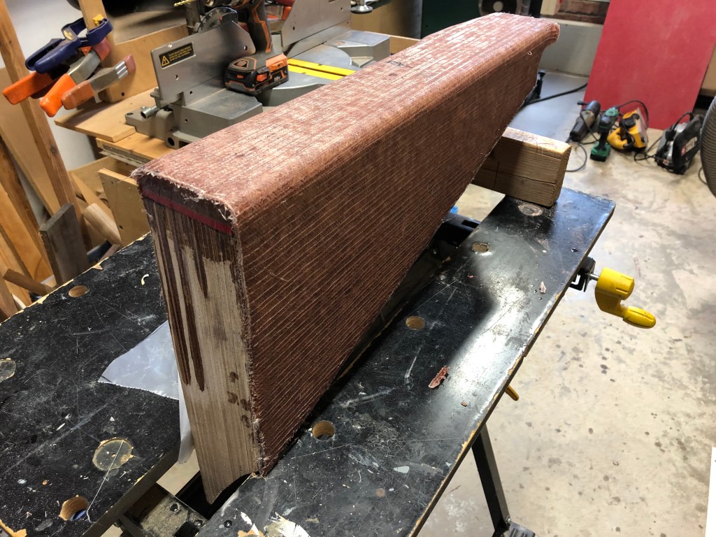
I took the top of the rudder that I cut off (let’s now call it the skeg) and glassed over the foam filled core inside. I also added flared sides to each side of the skeg to span around the rudder post. Back at the boat I sealed the top of the rudder and its foam core by epoxying a 1/4” thick piece of pre manufactured fiberglass to the top and filling the edges with thickened epoxy.

The next step was to epoxy the skeg to the underside of the hull above the rudder. I beveled the edges of the skeg and the hull and applied thickened epoxy. In other words, I transferred the top of the original rudder (the part I cut off) to the underside of the hull. I reasoned the area I removed was so small there would be no noticeable effect due to the slightly smaller rudder. Also, it’s important to point out the rudder benefited in additional control surface when I filled in the aperture back in 2010.


I needed to bridge the gap between the front end of the new skeg extension and the hull. I played around with a few ideas finally settling on 1/4” blue board that I cut and shaped to fit. I covered the blue board with packing tape and smeared it with paste wax so the epoxy would not stick to it. I positioned the blue board and laid on two layers of 1708 biaxial. Once it was cured I pulled out the blue board. I carefully trimmed up the epoxy until I had it the way I wanted.

I ordered some 3/4” thick manufactured fiberglass sheet from McMaster Carr. I designed a support bracket for the shaft log that would lock the shaft log to the new skeg. I cut the fiberglass on my table saw with an old thin kerf blade. I test fit the pieces at home then took them to the boat and shaped them for a precise fit. Once satisfied I bolted and epoxied the support through the new skeg extension.


Finally, it was time to permanently install the shaft log. I desired the shaft log to extend into the boat only as far as necessary to accommodate the stuffing box. The more shaft log in the boat, the further forward the engine would have to be positioned which would create additional challenges for the companionway ladder. Every step had to be considered in a holistic manner. I cut some 2x4s to use as “dead men” to hold the shaft log in place. I needed a cool day to keep the epoxy under control as mixing large aamount creates significant exothermic heat. I mixed up batches and thickened it with colloidal silica. I used large plastic syringes to forces the epoxy into the gaps around the shaft log. Once the epoxy began to tack up I began applying four layers of 1708 biaxial which I had precut to fit in an overlapping manner. I carefully squeegeed out the excess epoxy and covered both sides with peel ply. It was a very long day. I finished in the dark.
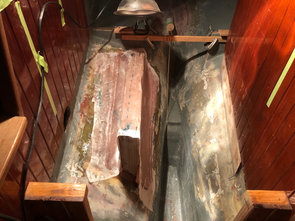
After pulling the peel ply I spent a couple of days fairing in the cured biaxial.

With the shaft log installed, it was time to work on the engine beds.
The shaft long and associated stuffing box became the key reference point for the placement and position of the engine beds. The reality is when I positioned the shaft log I had a very firm grip on where the engine beds would be. In fact, because I had redesigned the galley and relocated the oven to where the ice box had originally been I had very little room to play with. The inboard side of the oven encroached into the original engine space 6-8”. The engine would also be angled towards the port side about 5 degrees.
To ensure the engine beds would be positioned correctly I built an engine template based on a design Tim Lackey uses when he installs engines for his clients. Beta Marine is just up the road from us and Farron Peffer was kind enough to loan me some used engine feet. Bolting the feet to the template really helped me understand exactly how to make the engine beds.
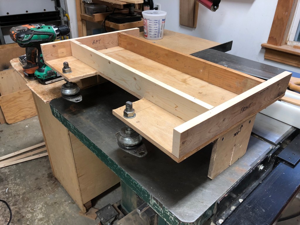
The template was a straight forward project but figuring out how to line every thing up and get the measurements for the beds took a while and a lot of thinking and fiddling.
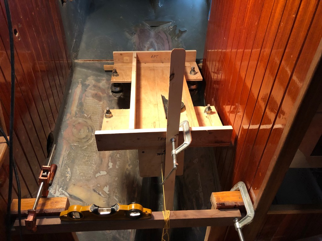
Once I figured out how to secure the template in a solid and stable position I built wood plugs for the shaft log, one for each end, carefully drilling a hole in the center of each plug. The hole in the forward plug a little bigger. I ran a string through the plugs and then through two wood brackets I attached to the template front and back. The brackets depicted the precise centerline of the transmission coupling with the centerline of the engine. When I pulled the string tight I kept repositioning the template until it did not touch the sides of the hole in the forward plug in the shaft log or the notches in the wood brackets representing the centerline of the crank shaft. When aligned as such I could then take measurements below the bottom of the engine feet so I could make the beds. I used strips of doorskin ply and a hot glue gun to make the templates.
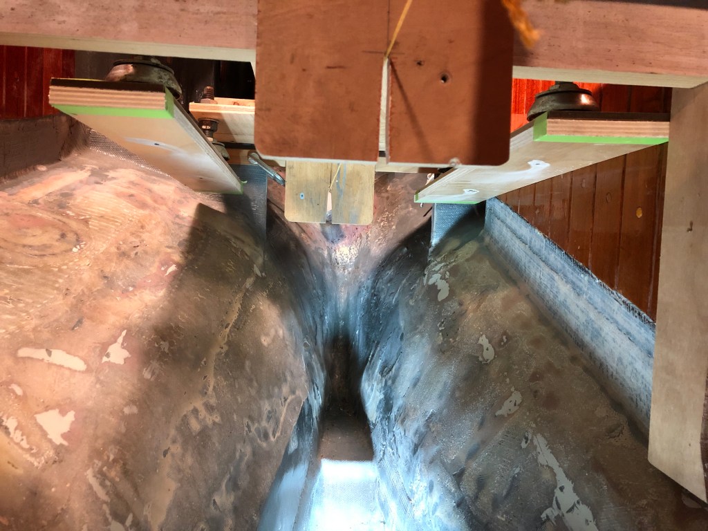

I made the beds by epoxy laminating six layers of 1/2” BS1088 Marine plywood for the starboard bed and seven layers for the port bed. I used the templates to draw layout lines on the laminated plywood then used a jig saw to rough cut the beds to their basic shape.

I took the beds to the boat and over a couple hours I was able fine tune the shape of the beds to fit against the hull nicely. I first positioned the port side bed as it was going to be bolted through the bulkhead that also supported the oven on the opposite side. With the port bed in place I bolted the starboard bed to the engine feet. I made sure the engine template was correctly aligned. It took a little time but using a slip of paper to find high spots and a 36 grit abrasive flap disk in a 4.5” high speed grinder we ended up with a great fit. The string remained perfectly positioned between the shaft log plug and the engine template alignment brackets.
With the port bed temporarily bolted in place I tackled the tricky starboard bed epoxying it in place using West Systems Six10 premixed epoxy in a cartridge dispensed with a caulking gun. I left it to cure overnight. The next day I rechecked the bed and it had cured perfectly level and plumb.
I removed the engine template and the plywood cleats screwed to the feet. I laid the G10 on the beds and repositioned the engine template and everything looked good. I removed the template and also the port bed and took it home to lay on the biaxial there as I couldn’t cover both sides of the bed with one side of the bed bolted to the bulkhead.
I needed four layers on the bulkhead side to provide enough of a spacer against the bulkhead so the aft rear foot would have sufficient bed width to sit on—remember the engine is canted to port. I also needed four layers on the top since I allowed for the extra 1/4” height. The biaxial over the top secures the G10 top plate to which the engine is bolted—that and the bronze plates layered under the G10. The base of the bed will be epoxied to the hull and bolted to the bulkhead. Then, additional layers will be laid on to the hull and up the side of the bed to the stagger line on the inboard side.
The laminating schedule for port bed was two layers 1708 on bulkhead side extended over top to inboard edge of G10. Then, two more larger layers over bulkhead side over top then down inboard side and staggered. The stagger will allow over lapping layers later from hull up to the stagger line with having a rough uneven seam.
The next day Gayle and I went back to the boat. She helped me apply four layers of 1708 biaxial to the starboard bed. We also applied peel ply to help the biaxial cure with a smooth finish.
Before I could install the port bed I wet out the 3/8” plywood shim I had previously epoxied below the staving to make the bulkhead flush down to the hull. I wet out the underside of the bed that fits against the hull. I also wet out the hull with slightly thickened epoxy. I applied two tubes of West Systems Six10 epoxy to the underside of the bed. I just gooped it on. I applied some thickened epoxy to a selected portion of the outboard side of the bed that fits against the plywood shim below the staving. Then, I set the bed in place and ran the bolts through the bed and the bulkhead. I tightened the nuts and used a radiused squeegee to spread the squeeze out into a nice filit.
Next, I wet out the three layers of 1708 biaxial I cut the day before. I applied them in sequence with the largest applied first. I carefully squeegeed the biaxial eliminating any air bubbles. Then, I applied a layer of peel-ply.
Last, I added a single layer of 10oz biaxial to the forward face of the starboard bed to seal the last exposed face of the plywood beds and covered it with peel-ply as well.

After pulling the peel-ply I spent a couple of days fairing the beds to get a smooth finish. I used West Systems epoxy mixed with 406 and 407 medium density fillers. Occasionally, I used 410 microlight filler for ease of sanding.
Phase I of the engine installation is essentially complete. The rudder has been modified. The shaft log has been installed. The engine beds have been installed.
But there is more to come. I have already designed and installed a 19.7 gallon diesel fuel tank, a fiberglass drip tray that fits between the engine beds, a rack for the 70 lb Luke storm anchor that fits along side and below the engine, and the engine intake through-hull and supporting seacock. I will be writing about all that and more in the next post.

John,
thanks for the detailled installation guide. Did you use wood or metal drill-bits/see saw for the shaft piercing?
Best,
Pier
jeandusud.com
LikeLike
I used metal cutting bits often call jobber bits just longer–maybe 10-12″ long. The 1″ hole I cut with bi-metal hole-saw like you would find at home building supply (Home Depot or Lowes).
LikeLike
Pingback: A Great Engine Install Guide – S/V Jean-du-Sud