
Installing an engine requires a number of supporting projects. In Part I, I described how I modified the rudder, installed a shaft log, and built and installed engine beds. In Part II, I will describe how I designed and installed the fuel tank; designed, fabricated, and installed brackets to secure the Luke 70 pound storm anchor; designed, fabricated, and installed a removable engine drip pan; and installed the engine intake flush through-hull and seacock, as well as a few other ongoing projects.
One of my concerns about installing an engine in the boat is the loss of precious space. We have all kinds of storage on the Far Reach and while only a small part of gaining it was a result of sailing without an inboard engine losing any of it remains a concern. Most of our storage space was created by redesigning the interior layout. But, it stands to reason that there will be some loss of space installing an engine and it’s components. However, my thinking has been if I am careful and thoughtful and don’t get in a a rush I can make this work with minimal loss of space. Case in point–the fuel tank.
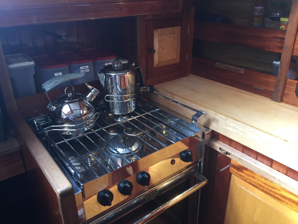
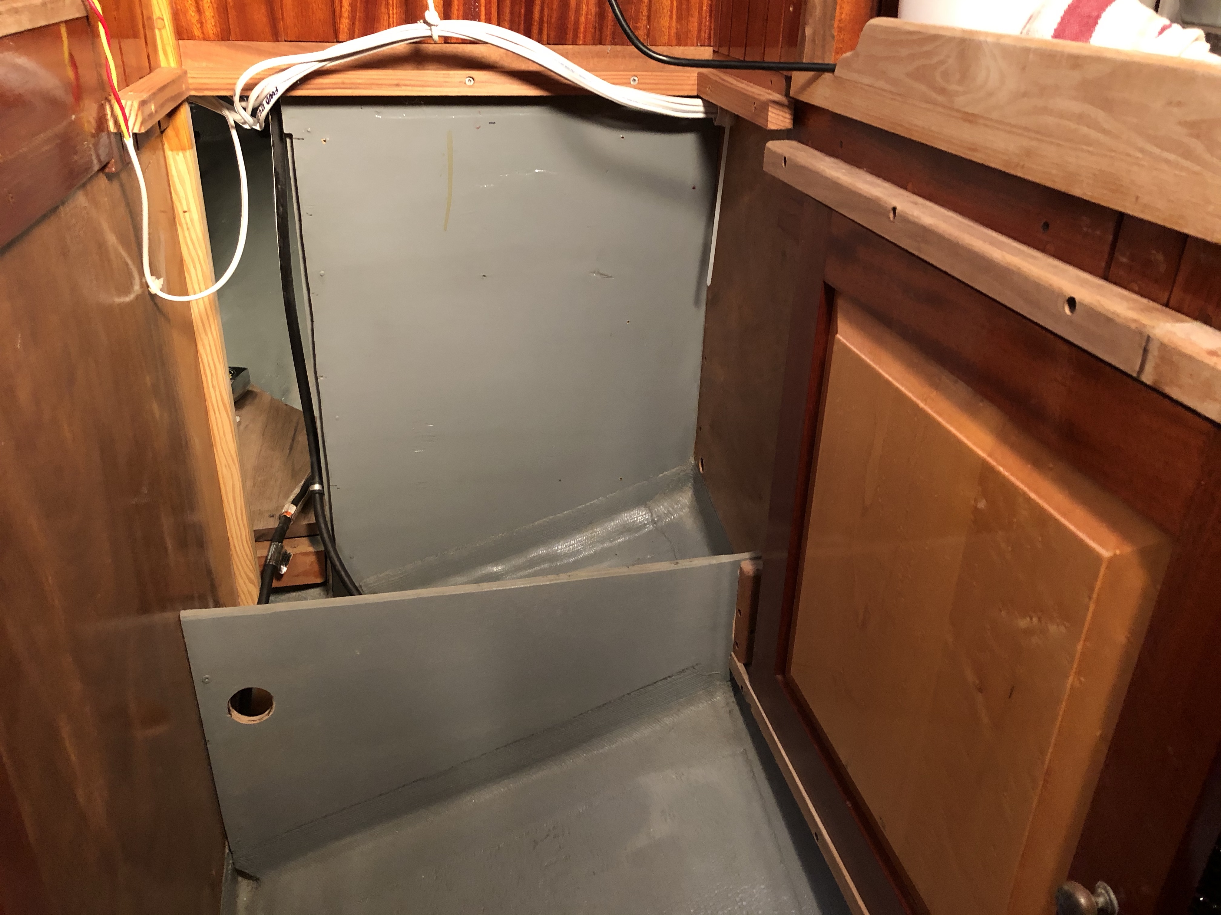
Behind the stove there is a shelf and under it is a 12″ deep, 24″ wide, and 26″ tall space that is essentially an empty void. We can access the space two ways: via the original engine compartment to the space under the cockpit sole or by crawling down through the port cockpit locker and into the space under the cockpit locker. Mostly, we stored in there a large bag of extra zip lock bags and things like that. Once I install an engine, the space behind the stove is not going to be very accessible. Thus, I felt like it would be a good place for a fuel tank. It’s not too far off the center-line and being under the bridge-deck it would lend itself to a vertical fuel fill with the fitting on the bridge-deck itself. So, I took the stove out and began measuring. First, I determined the cubic inches a certain size tank would comprise. Second, I converted the cubic inches to gallons and determined that it would hold about 20 gallons which was my target capacity. Last, I made a mock up what I thought would fit in the space.
Lots of folks seem to want as big a fuel tank as they can fit in their boat. They approach the engine size the same way. But, I am going to a lot of work to keep the boat as simple as possible and maintain the sailing performance of the boat above all other things. So, for me it is about the smallest engine and fuel tank that will be practicable.
Let’s digress for a moment and talk about engines since I did not include that discussion in the Part I post. My target cruising speed on flat water is about 5 knots. Theoretical hull speed for the Cape Dory 36 is 7.8 kts. The difference in horse-power required to get from 5 kts to 7.8 kts is dramatic. Basic calculations using an online calculator reflected I needed only 12 hp with a 2.6:1 reduction gear turning a 15.5″ diameter two blade folding propeller to attain a speed of 5 kts in flat water. So, 12 horse power was my starting point. And 12 hp is close to my experience using the Honda 9.9 hp outboard on the Far Reach. At 3/4 throttle with a 10″ diameter 4 blade propeller turning about 4000 RPM we made 5 kts. At wide open throttle, about 5500 RPM we made 6.0 kts. It surprises a lot of people we could attain that speed using a 9.9 hp engine pushing an 18,000 lb fully loaded cruising sailboat. We never felt like we did not have enough hp. If there was wind, we were sailing. It does not take a lot of horse power to move the boat up to 2/3s of hull speed in flat water. But, I also did not want to run a diesel to its max of 3,500 RPM to get that 5 kts, so I knew we needed some amount of horse power more than 12 hp. After a lot of reading and thinking I initially settled on a Beta 20 HP three cylinder diesel.

I read the specs for the 20 HP and it seemed to be able to do what I wanted at about 2,000 RPM. Fuel consumption on the performance chart was just under one liter per hour at 2000 RPM. With 18 gallons of usable fuel that gave me a theoretical range of 340 nm on flat water. So, let’s call it 300 nm. Keep in mind the boat came with a 50 HP Perkins and a 50 gallon fuel tank. The Perkins 4-108 burned a gallon per hour at 7 kts. With the original 50 gallons tank I had a range of about 320 miles, about the same range as the 20 hp. Of course I could maintain better speed with the Perkins under conditions that would degrade the performance of the smaller engine. But, remember, my priority is enhanced sailing performance with a goal of 5 kts on smooth water. I’m a sailor, not a power-boater.
I visited the Beta Marine US importer and discussed my plan with Farron Peffer. I learned the Beta 25 hp has essentially the same foot print (3/4″ longer) as the Beta 20 hp–same width and height. The Beta 25 is a slightly heavier though–260 lbs vs the 230 lbs. Farron was adamant…there is no space saving of the 20 over the 25 HP. The cost difference is $300. The power output graph for the 25 hp reflected 12 HP at about 1,600 RPM and less than a liter per hour fuel consumption at that RPM. Thus, I selected the 25 hp not because I needed it but because there was really nothing to gain by going with the 20 hp. Fuel usage at 12 hp is the same as for the 25 hp as for the 20 hp. So, with a tank less than half the size of the original 50 gallon tank, and an engine less than half the size and weight of the Perkins, the range should be about the same. The smaller engine and fuel tank would take up less space and we would see a weight saving over the original propulsion system of more than 500 lbs! We also end up with some reserve power as the Beta 25 has more than twice the hp we need to reach our goal of 5 kts on flat water.

Another consideration for me is fuel stability. Diesel fuel does not like to sit unused. Water collects in it which is not good for an engine. If unused, microbes start growing in the fuel and settles to the bottom of the tank which then gets sucked up via the fuel pick up line and clogs the fuel filters. I really don’t see myself using much fuel. An engine is just not my way. During my last six month cruise to the Virgin Islands I think we used about four gallons of gas and most of that was just idling. So, a smaller tank is less likely to cause me problems because the fuel is used quicker relative to its smaller sized tank. Thus, it gets replaced with new fuel more often. It is also easier for me to refuel a 20 gallon tank with a single five gallon jerry jug, my preferred method, than to take the boats along side a fuel dock. One jug of fuel fills the tank 25 percent of the way. For me, once again, less is more. I fill the water tanks the same way, though I carry (5) collapsible five gallon water jugs to keep the water tanks topped off. One dedicated diesel jerry jug can be stowed below when not used. There will be no diesel fuel jugs stowed on deck.
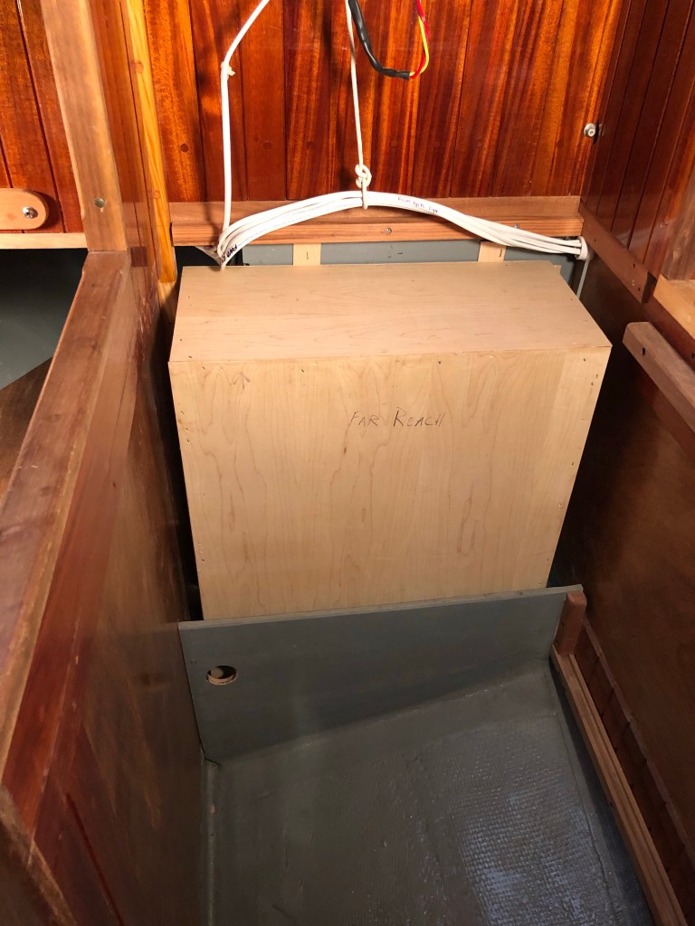
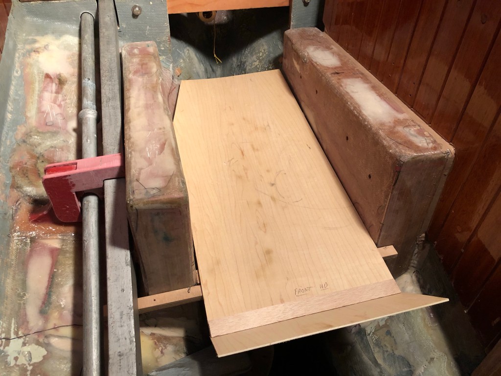
Back to the fuel tank. I thought a tank capacity in the 18-20 gallon range would work for the Far Reach. So, I drew out the dimensions. Then I made a mock up with doorskin plywood and took it to the boat.
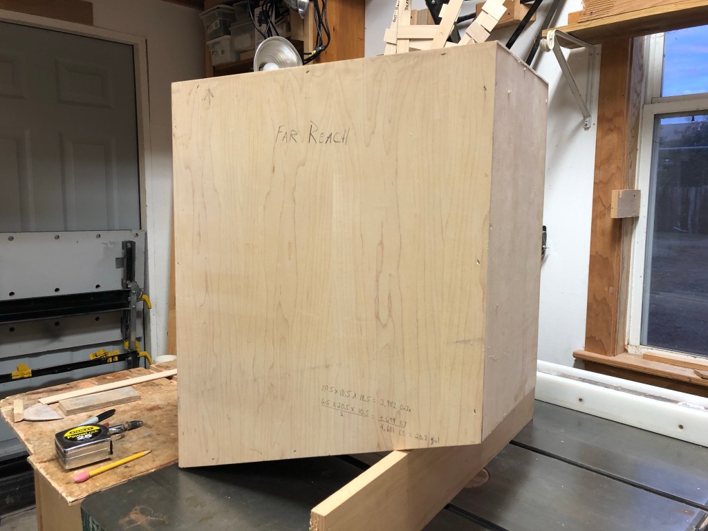
Not only did the tank need to fit the space, I needed to be able to install it and remove it without it being a big hassle. The tank fit fine. Easy to install. Easy to remove. Calculations reflected it would hold 19.7 gallons. Perfect.
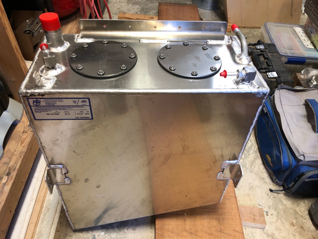
I contacted several tank builders. I asked for quotes. They were all about the same…about $500. I decided to go with Florida Marine Tanks because they had a good reputation and they were located in…well…NC. Made perfect sense. A two hour drive from home to their business would save a fair amount on shipping cost. They were easy to work with and agreed to install a full baffle with two clean-out ports. I emailed my drawing and they turned it into a CAD and sent it back for me to look over. I chatted on the phone with the engineer. We made a few changes. I was impressed with their professionalism and their interest in my concerns.
I had to wait a month to get the tank. So, in the mean time I purchased some African mahogany and milled some of it for interior staving since I would have to rebuild the entire area under the companionway to accommodate the engine. I spent time making drawings of how I could keep the walnut work bench and pull out drawer I had grown accustom too. I developed a plan that allowed me to cut down the mahogany and teak ladder I used for the last five years using only the first step.

I purchased the iroko for the rubrail, which I will install later in the summer. I removed the eight breaker 12v electric panel and brought it home. I decided I wanted to move it over the top of the engine. I only use four breakers so I felt like it would meet my needs but I wanted it in a more convenient location.
I also ordered LED running lights since I felt that my argument for the kerosene navigation lights would be a tough one to win with the authorities once I installed the engine and a second battery. Without an engine, I always felt I was on solid ground since there is a provision in the Coast Guard International and U.S. Inland Navigational rules (Annex I, para 11) provides for non-electric navigation lights. I searched long and hard for several months to find quality lights that looked like they belonged on the Far Reach. Then, my friend Kaj Jacobson recommended a set of bronze lights made in Italy that can be converted to LED. Leaving behind the kerosene navigation lights and adopting LED was part of the treacherous design spiral that can pull you off your path of simplicity afloat. One step towards technology can lead to another and another and so on and so forth. In this case, the LED lights made sense…so I took a step in that direction.

With the breakout of the Corona-virus I decided to pay for the Beta 25 engine not knowing if production would shut down and availability would evaporate. The US distributor is just up the road from us in Oriental, NC. They agreed to let me store the engine in their warehouse till I was ready to install. I upgraded to the 75 ah alternator, the 2.6:1 reduction gear (so I could incorporate a bigger higher pitched two blade folding prop, the high-rise exhaust elbow, and the deluxe instrument cluster. When I paid for the engine I brought the instrument cluster home so I would have it on hand when I redesigned the 12v panel that would contain both systems.

I will mount the engine gauges below deck where they will not be harmed by the occasional cockpit full of water which is not uncommon sailing offshore. Plus, I just did not want to see that stuff when sailing. The only instrument I want to see when sailing is the compass. What gauge do I need to stare at when motoring anyway I can’t just as easily see by ducking my head in the boat and looking under the bridge-deck. Keep it simple.
Finally, the tank arrived. The quality of the work was excellent. It fit perfectly. I bolted it in and ran the 12v wiring that supports the LED cabin lights and the 12v drops across the top and protected them with a full length split chafing hose.


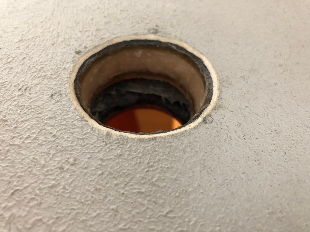
I cut a hole in the bridge deck, dug out the core, and back filled it with epoxy. I found the original bronze Spartan Marine diesel fuel tank fill cap that came with the boat and installed it in the bridge deck directly over the fill.

I also found the bronze fuel vent and set it aside for installation when it’s time to run the tank vent line. I had specified the location of the fill pipe in the tank so I could sound the tank with a wood dip stick marked to reflect the fuel level. Fool proof. I installed the fuel fill hose which will be concealed by a varnished mahogany box.

The Racor 500 fuel filter, the Groco raw water strainer and seacock, and the new battery switch arrived. I set them aside until I completed other tasks.

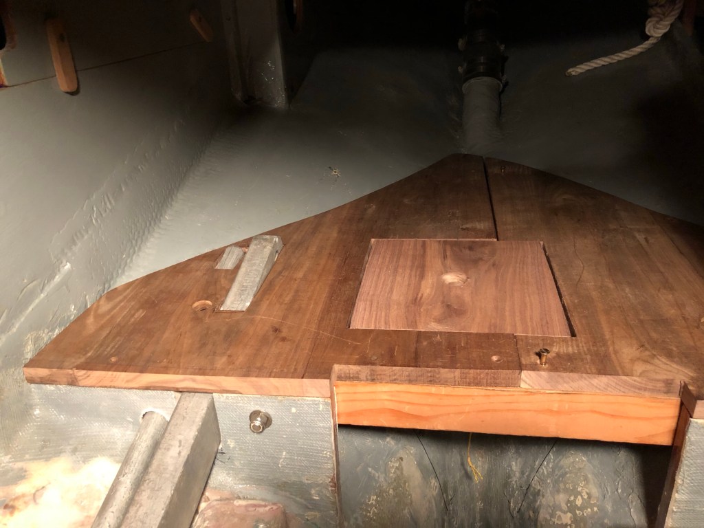
I had concerns about having quick access to the stuffing box so I built an access opening directly above it in the walnut sole, the aft part of which I was able to keep in place.
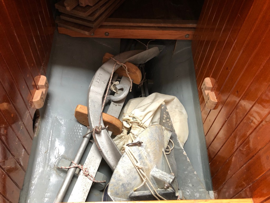
With the tank installed I went to work on two projects at the same time as they each affect the other. One was a storage rack for the three part Luke 70 lb storm anchor I carry on the boat. It is a beast and I would not think of not having it aboard. But, it’s big and heavy and for the last five years I had stowed it along with a back-up 35 lb spade, 35 lb CQR, 40′ of spare chain, extra anchor shackles, and an 8′ drogue parachute anchor in the compartment that now will be occupied by the diesel engine.
I wanted those items down low not only to increase stability of the boat but also because they can make up a little for the fact the Beta 25 hp engine is about 12″ higher in the boat than the original Perkins 50 hp engine. It’s important to remember I removed a lot of components from the Far Reach during the rebuild. And, though those things weighed a lot, they were part of Carl Alberg’s trim calculations. I removed the steering wheel, it’s pedestal, and all the heavy under cockpit steel hardware that supported it when I converted to tiller steering. I removed a 550 lb engine and all of it’s associated wiring and components– water lift muffler, three blade propeller, prop shaft, batteries, etc.
Five years ago I compensated for removing that weight by casting ten 25 lb lead pigs and stowing them low in the bilge under where the Perkins engine had been. Along with the ground tackle I mentioned earlier, I also installed, adjacent to the engine compartment, a 40 lb Edson bronze #117 gallon-a-stroke manual bilge pump.

I built and installed the propane locker for three 10 lb propane bottles in the aft end of the cockpit. I stored a six gallon gas can for the 9.9 outboard (when I took it along) on top of the propane locker. With all that, we were still a little light in the stern. The new Beta 25 will just about swap one for one with the lead pigs. The 20 gallon fuel tank will swap about even with the 9.9 honda four stroke (which by the way was stored high up at life line level) and the six gallons of gas. The diesel tank will sit lower in the boat than the items it replaced. It’s going to all work out about right.
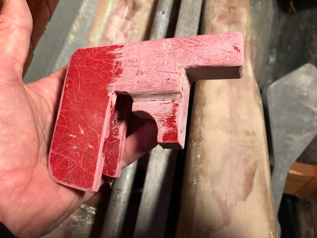
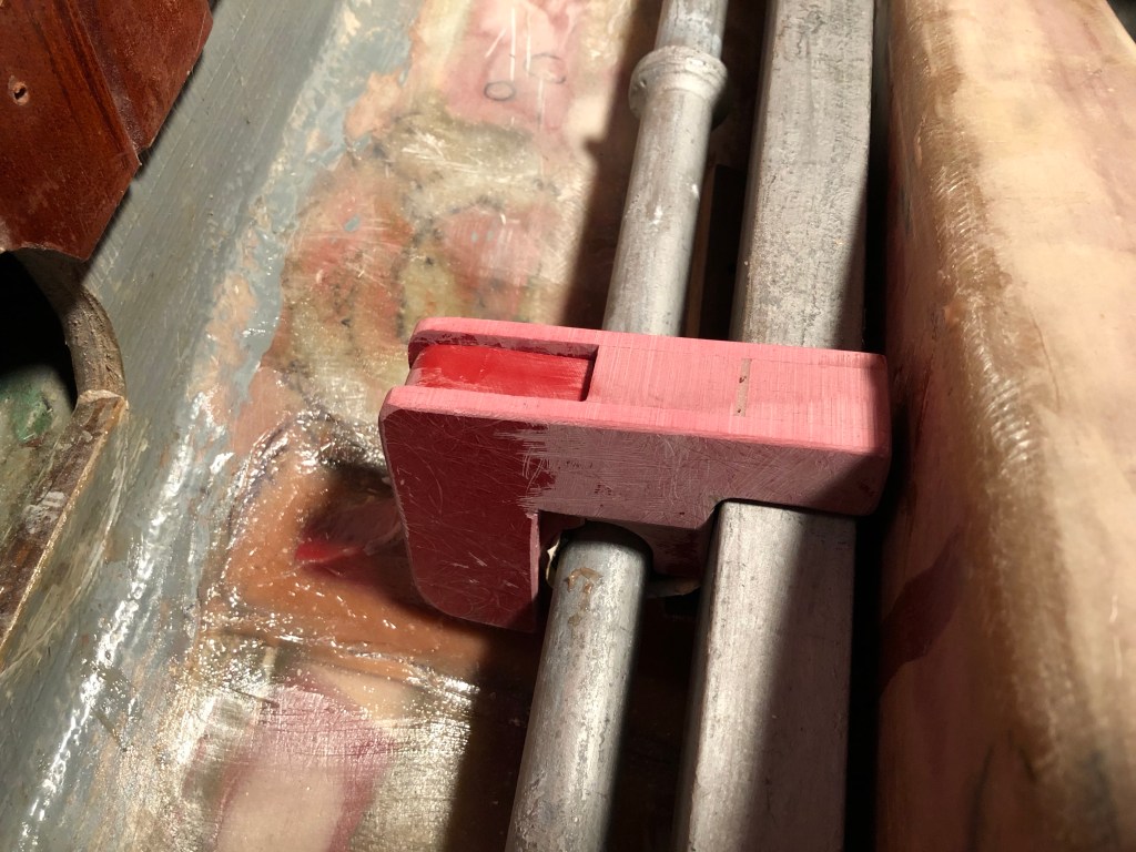
For storing the Luke storm anchor I tried a couple different solutions. Once again a simple mock-up quickly showed me the first plan was no good. But, the next idea turned out to be the answer I was looking for–the stock and shank to the outboard side of the starboard engine bed and held in place by a bracket clamp I fabricated from manufactured fiberglass sheet.
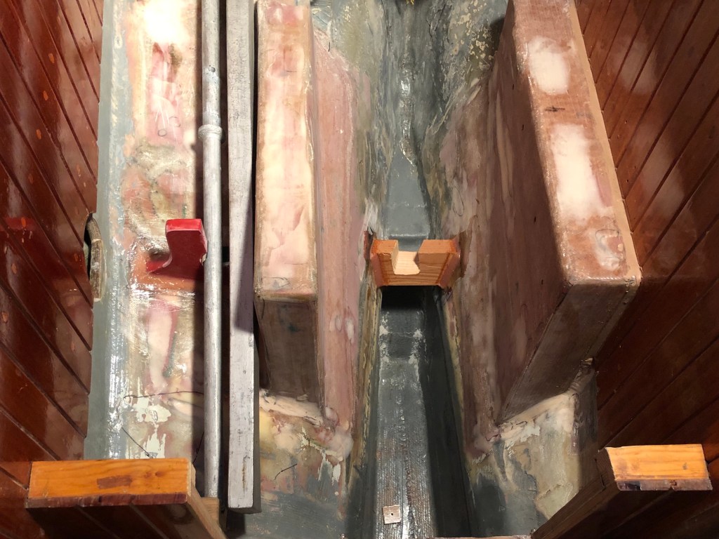
I had to modify the walnut sole behind the engine to accommodate the stock and shank length. A minor but necessary compromise.
The fluke required more drastic action. It’s quite heavy and I wanted it low and out of the way. I epoxied in two wood brackets low in the bilge and covered them them both with 10 oz biaxial. I don’t want that thing coming lose (it will be tied in just as before) if we get knocked down or god forbid worse. There is still room under the fluke for the 35 lb spade and my canvas bag of spare chain and galvanized shackles. I’ll eliminate the 35 lb CQR from our inventory for now.

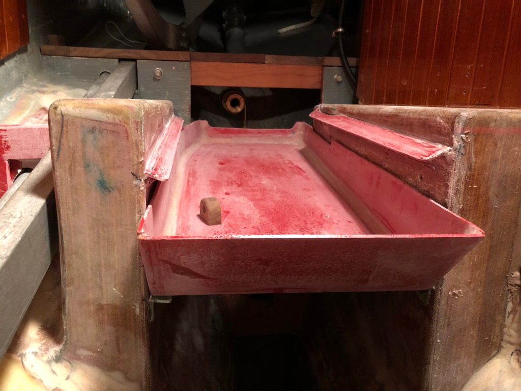
The key to being able to stow the big fluke between the engine beds was incorporating a removable engine drip tray. A drip tray was essential. Not only has the Far Reach had a completely dry bilge for five years, it is also spotless. I do not want oil or other engine fluids in the bilge or on the things I store under the engine. I tried various ways to fit the Luke components in the compartment but was not satisfied. Then, it occurred to me the drip tray could be removable which would opened up significant space under it. How would I do that? It took a while to figure it out. Just thinking and drawing and fiddling. I made a mock up and played with it to I fleshed out how it would work.

There is nothing like an accurate mock-up to reveal things well beyond your ability to imagine in your head. With a mock-up the solution revealed itself. I went to work. It was not difficult. I don’t really like working with fiberglass but I have to say it is very practical and not difficult once you understand it and develop some basic skills. Of course, by now, after the six year rebuild and many gallons of epoxy and yards and yards of fiberglass cloth I have more than just basic skills. But, working it is still not pleasant like working with wood. Just the way it is.
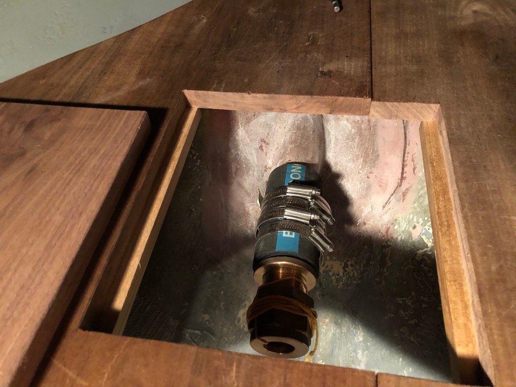
Next, I decided where the intake through-hull and supporting seacock needed to be located. But, I also wanted to install a flush through-hull. Why? Because they are more streamlined. In fact, when I purchased the Far Reach in 2001 she had 10 through-hulls. Why do people install so many holes in their boats, not to mention create all the drag associated with those mushroom through-hulls? I don’t think most sailors think about the drag. Water is something like 700 times more dense than air. Wave your open hand fast through the air. Easy. Now try it in the water. Big difference. A smooth and fair bottom is significantly less drag on the boat. During the 2008-2015 rebuild I eliminated the large propeller aperture and all but three through-hulls and sailed her that way for five years. But they were standard mushroom style. During the rebuild I explored how to install flush through-hulls. But, I couldn’t figure out how to create the precise beveled recess to match the design of the flush through-hulls fittings. I had too many other projects to get stuck on it. I let it go. This time, not only did I install a flush mounted 3/4″ engine intake through hull, I came up with a way to convert the existing through hulls to flush style which I accomplished with about 4 hours of work. But that is a separate post for another time.
It was time to install the seacock. There was no question I was going to go with the Groco IBVF two part base and simple ball valve designed to work together. It’s a relatively new product and far exceeds ABYC standards for seacocks. I wrote about them in the rebuild blog which you can find here.
I looked over the engine diagram to see where the raw water intake was located. I positioned the seacock in various places but knew it needed to be quickly accessible because I would need to close it to clean the raw water strainer should it get fouled while under power. I made the backing plate same as for the other three seacocks—1/2” thick G10 epoxied to the hull. Once I determined the location I drilled the hole. I spent a day or two solving how to install the flush 3/4” through hull, then epoxied in the G10 base, and installed and bedded the seacock and through-hull.

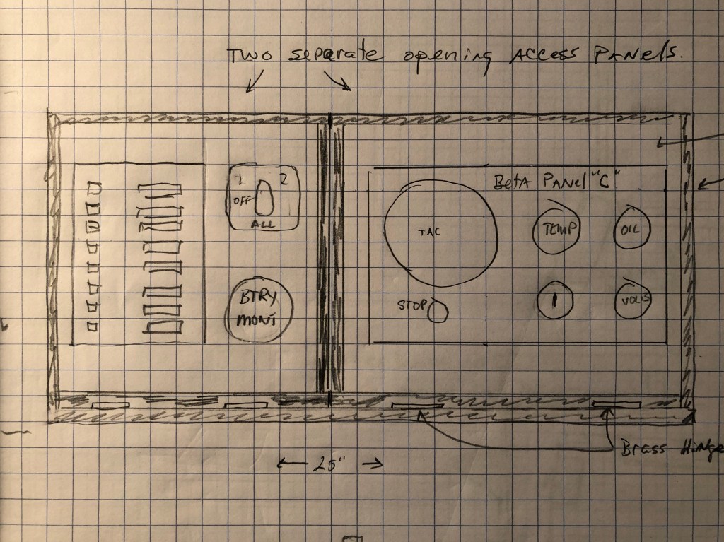
What’s left to do? Well, I need to design and relocate the 12v panel which, as previously mentioned, will also support the engine instrument cluster. I need to paint the engine compartment and drip tray. I also need to install the LED navigation lights. Then, of course, I need to install the engine, prop shaft, propeller, exhaust system, throttle control, and battery. Finally, I need to build the forward end of the engine box that will conceal the engine, support the work bench and drawer, and the companionway steps. All that will be covered in Part III.
