
Building and Installing the 12v panel and Supporting Systems.
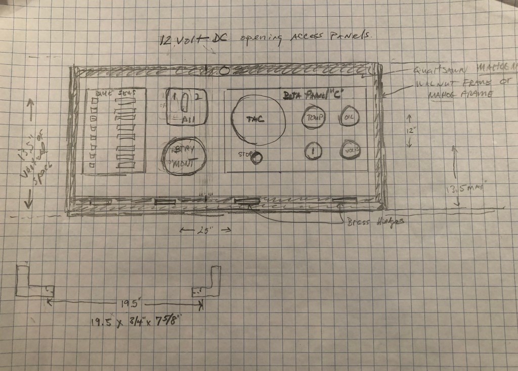
With the engine beds installed it was time to start work on the new larger electrical panel to replace the small one I used for the last five years. I decided to reuse the 8 breaker Blue Seas 12v panel. I only used four of the breakers before: 12v accessory plugs, LED lights (which I added for the second voyage to the West Indies), AIS, and compass light. I also decided to move the panel from its previously hidden location near the inboard side of the quarter berth to under the bridge-deck, where it would be more accessible, and combine it with the Beta Marine engine instrument cluster, battery monitor, and battery switch. The new panel will be hidden by sliding doors.
I decided the panel door should be solid mahogany (no plywood) to include the rails and stiles. I also wanted it it to be hinged on the bottom. I would also install bare walnut trim around the door in keeping with the general interior design throughout the Far Reach.
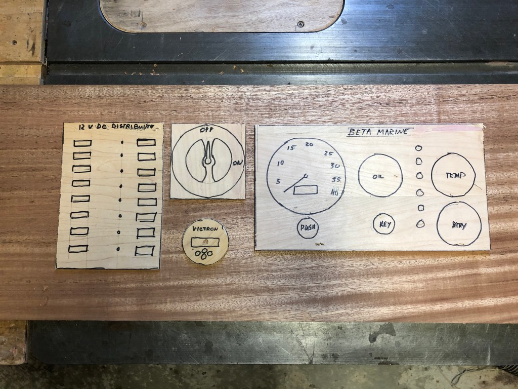
To start the project, I cut a piece of doorskin ply to represent the usable part of the panel then made templates for all the instruments and components to be mounted on it. Everything seemed to fit.

A thought I want to offer to those reading this post is you can complete projects like this without spending a whole lot of money. It is far less expensive to make things yourself than pay some one to do it. With patience and practice you can produce far better results than the average “tradesman.” The mahogany I milled for the rails and stiles cost about $15-$20. The walnut about $10. My labor was free. It would probably cost $300-400 to pay someone just to fabricate the panel and glue it up. True, there is some overhead in tools, but not as much as you think. My labor is free. My time would have been wasted watching TV or staring blankly at you tube or Face Book. It is the same philosophy I used to rebuild the Far Reach. I produced a wonderful boat for pennies on the dollar. Maybe it’s disingenuous to suggest anyone can do it, but I think most people can if they want to badly enough. Being able to rebuild, modify, or visualize what you want and then make it to a high standard is liberating and thrilling. So if you have the desire, I encourage you to break the bonds of being a consumer and beholden to those that seek to separate you from your money and present you with an inferior product.
Satisfied with the layout of the instruments on the template I milled a single piece of 5/4 28″ long 12.5″ wide African mahogany down to 5/16″ thick. It was a shocking waste of wood. If I owned a bandsaw I would have re-sawed the plank so I would have two thin pieces. But, I was eager to get going so I planed it down to the desired thickness. Though I wanted the panel to be thick as possible it had to work as a panel door. That meant it had to be thin enough to fit into the slots I cut in the rails and stiles. I might have gotten away with a 3/8″ thick panel. But, if the slots are too wide in the rails and stiles then they might not support the panel.
Next, I milled African Mahogany for the rails and stiles. I used a special router bit for cutting the slots for panel doors. I added shims to cut the slots for a proper fit–wide enough so the panel could float in the rails and stiles. Then, I checked the fit of the temporarily assembled rails and stiles to the space under the bridge deck.

After I milled the slots I laid the rails and stiles over the panel and cut the panel a little narrower and shorter than the distance from slot to slot so there was room for the panel to expand and contract. You don’t need to allow much for length because wood movement with the grain is minimal. Because the panel is quartersawn, vice plan sawn, it won’t move much but you always have to allow for some wood movement.

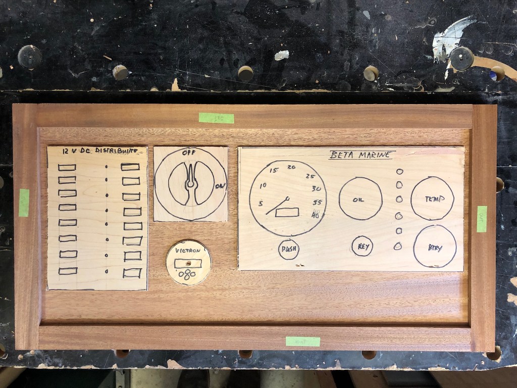
Next I assembled the panel into the slots and cut templates for the instruments and test fit them to make sure everything looked correct.
switch or USB charging port.
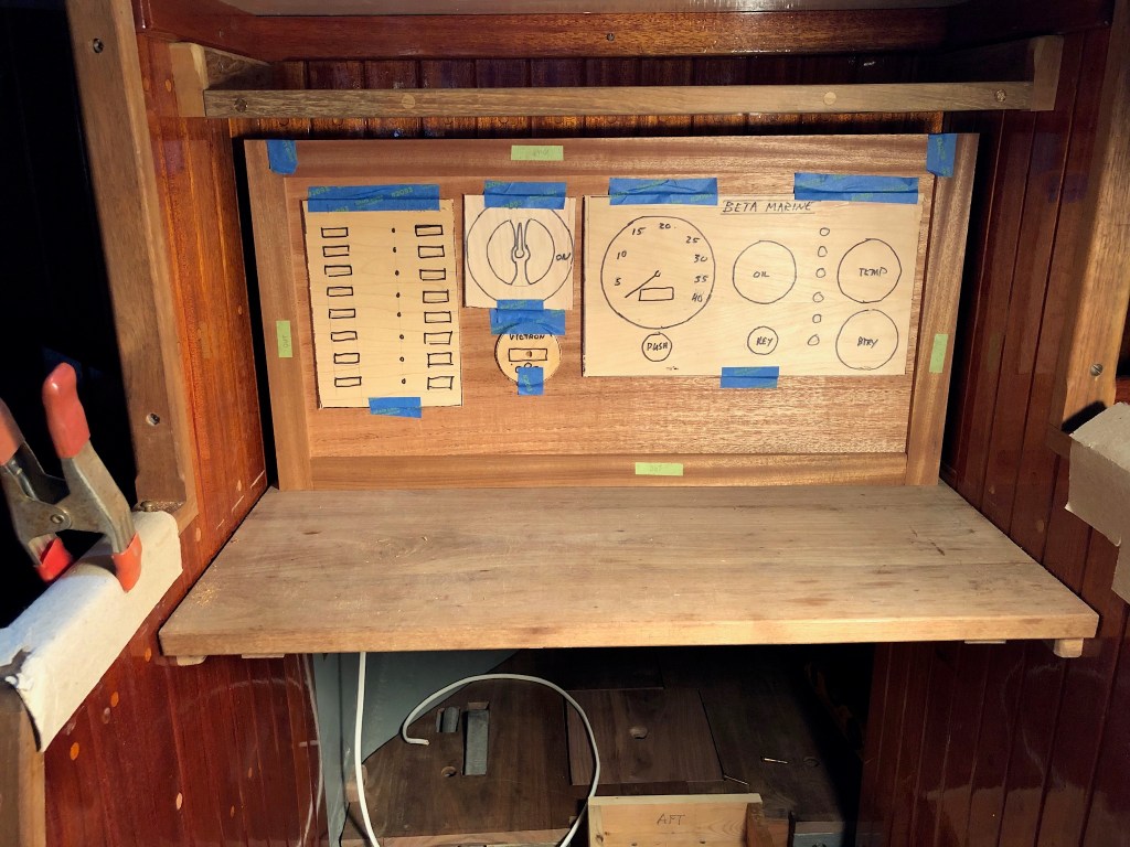
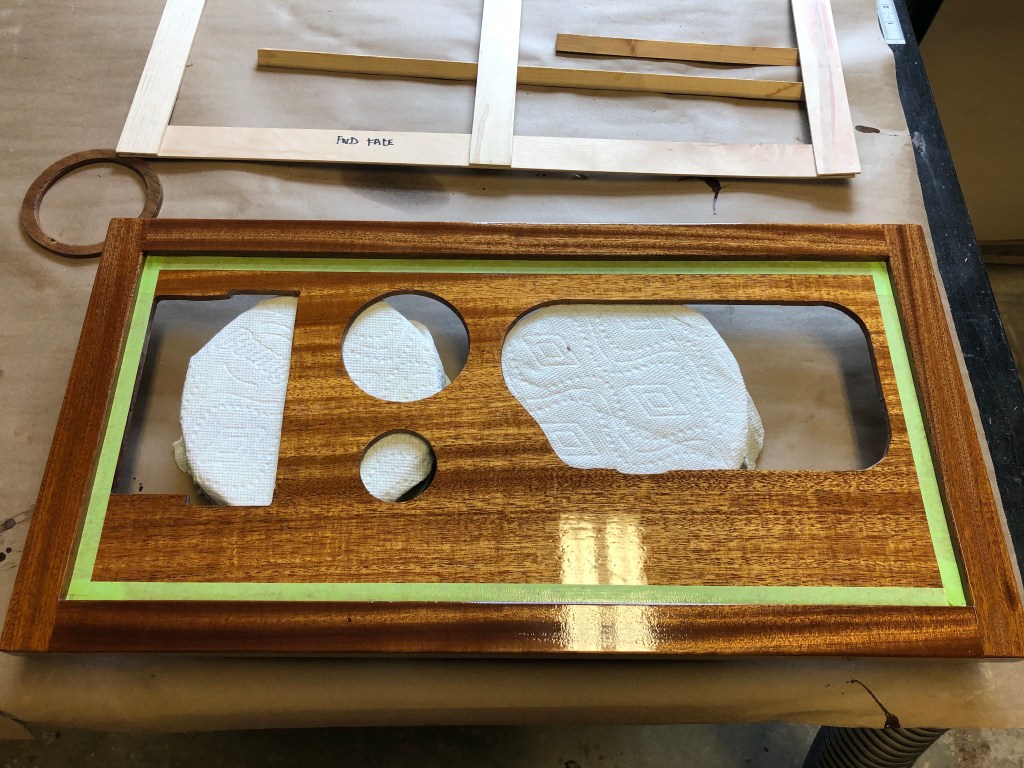
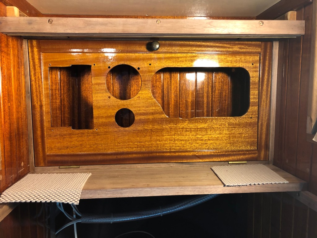
You can’t be too careful with projects like this. One forgetful moment or confused bit of math and you have cut your door too small. So, I took all the components to the boat and with some tape made sure they would fit as I envisioned. Note the gaps all around the panel which is part of the design. I planned to install bare walnut trim there to allow the door to be smaller than the bulkhead trim the door has to clear when open. Plus, you don’t want the door so close to the mahogany staving that you can’t get the door in and out without marring the varnished wood. Also, you can’t see it yet, but the top edge of the door has to clear the yet to be installed slotted track for the sliding doors that conceal the electrical panel.
With the early test fit complete I cut the holes in the panel for the components. A little nerve racking. But, it went fine. I still had not glued up the rails and stiles–just pushed together to see how it looked. I also needed to lightly radius the edges. Next, it was time to varnish.

This is probably a good time to explain the small number of breakers. Many people seem to want as many electrical components and systems on their boat as they can afford or fit or both. When it comes to sailing my philosophy is less is more. The less that gets between me and the boat, between me and the environment, between me and my decision making skills the more visceral the experience. Without the intimate connection between the sailor, the boat, the wind and water why even bother to go sailing?
I don’t have an electric windlass—I have a manual windlass. No spreader lights. I use a LED headlamp. No wired VHF. I use a battery operated hand held. No SSB transceiver. I use a portable battery operated SSB receiver. No chart plotter. I carry a hand held GPS and my sextant. No electric bilge pump. I rely on a bronze Edson model 117 gallon-a-stroke manual pump. I want sailing to be physical. That’s what I love about it. So, instead of the large DC panel I could install, I chose the smallest to keep things simple.
The bottom line…for me, the simpler my life, the happier I am. This extends to the boat. A general observation I have made throughout my life is that people—provided they are reasonably healthy, not in debt, have some money in their pocket, and have some friends—tend to be happier the less they have. Thoreau had it right, “Our life is frittered away by detail.” So did Hayden, “How much does a man really need….” And of course Herreshoff, “Simplicity afloat is the surest guarantee of happiness.” It’s also true some people need more…at least they think they do. Some people never have enough. So perhaps Shakespeare had it the most right, “to thine own self be true.” We all have to figure it out for ourselves. But I yammer.
I applied six coats of varnish to just the panel. Then assembled the panel and glued the rails and stiles together. I taped off the panel and applied six coats to the rails and stiles. Then, I removed the tape and applied one coat over the whole thing. The reason for varnishing them separately is if you apply seven coats of varnish over the joint between the panel and the rails and stiles, the panel can’t move to expand and contract. Also, you have to sand between every coat. There are no short cuts when it comes to bright work. That’s why they call it work. Total of seven coats.

I cut the walnut bottom trim then mortised it for the hinges. I test fit the panel again. There is some tricky geometry for the sliding doors to work. If I had made the panel a little shorter it would be easier but I wanted the panel to have room for some USB plugs or perhaps another switch or two in the future.

Next, it was time to work on the slotted walnut track the mahogany doors would slide in. In order to make the doors wide enough I had to resaw them on a bandsaw then plane and glue them together. Resawing just means to cut the plank in half width wise so you have two thinner planks. If the plank is thick enough you can cut it several times to get multiple planks from a single thick plank. You use this technique when the final planks are going to be thinner and it would be a waste to plane a thick board down for a smaller thinner one. I was lucky to get access to a bandsaw for this step. As you recall, when I made the panel I did not have a way to resaw the wood and I had to plane it all down.

To join the planks together I used a technique called edgeless joinery I learned from an article in WoodenBoat magazine years ago. It’s pretty simple. Just takes a router with a straight bit and clamped guide bar, then glue them together. For more info on this technique you can click here and read about how I built the top of the chart table. Scroll down about 2/3 of the way to find the details.

I wanted the doors to hide the electrical components but without drawing attention to themselves. Since the rest of the boat’s vertical surfaces are largely “V” groove I wanted the doors to be of the same style so they would better blend in. So, I needed to create V groove. To do this I used a small trim router with a V groove blade and a guide bar.

It is a similar technique to the method I used to make the V groove overhead plywood panels in the Far Reach. But, the doors are thin solid wood which can be difficult to stabilize so they don’t warp. My friend Kaj Jakobsen, a boat builder and a certified Swedish furniture maker, has taught me many interesting techniques. One thing he mentioned to me about thin solid wood panels is whatever you do to one side it’s a good idea to do the same thing to the other side so the wood receives the same stress and relief. So, I cut groves on both sides.
With the panel doors made I needed to cut the dados in the walnut that will serve as the track for the doors so they can slide back and forth.

Next, it was time to test fit the sliding doors. I had to temporarily install the walnut slotted track that holds the top of the sliding doors. I did not have the correct slotted flat head bronze screws so I temporarily used SS screws to keep the project moving forward.
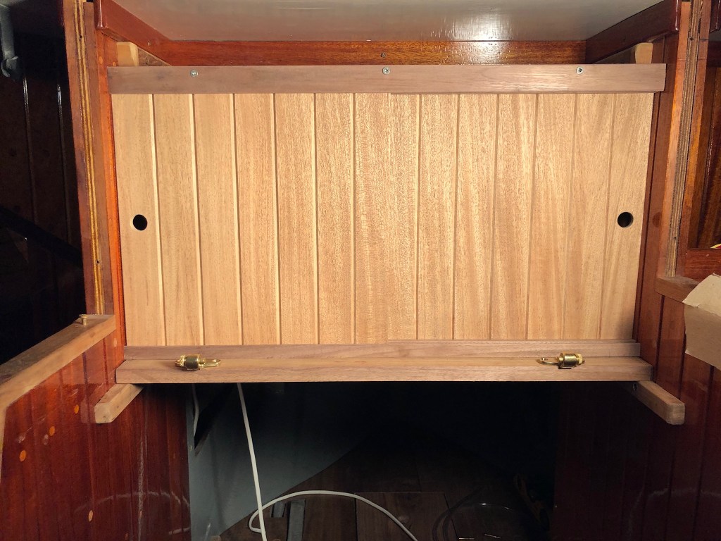
With the sliding doors trimmed so I could lift up on the door and slide it out of the track to remove it, I applied eight coats of varnish. While the varnishing was on-going I made a trim box to fit around the fuel fill hose that is positioned behind the stove.

The fuel fitting is on the bridge deck and the diesel tank is behind the stove. One of the things I like about this layout is I can use a marked and graduated “sounding” stick to determine how much fuel is in the tank. What could be simpler?

The trim box is held in place by a couple oval head bronze fasteners. This picture is a good example of how freshly milled and varnished wood is a bit lighter in color than older wood. It will get darker over time.
It was August and the temperatures were ridiculous in the boat. About 104° F. Every day I set up the canopy next to the boat so I could take breaks in the shade.


Satisfied with the varnish, I replaced the temporary SS fasteners with bronze slotted flat head fasteners. I installed bare walnut trim around the electrical panel door.

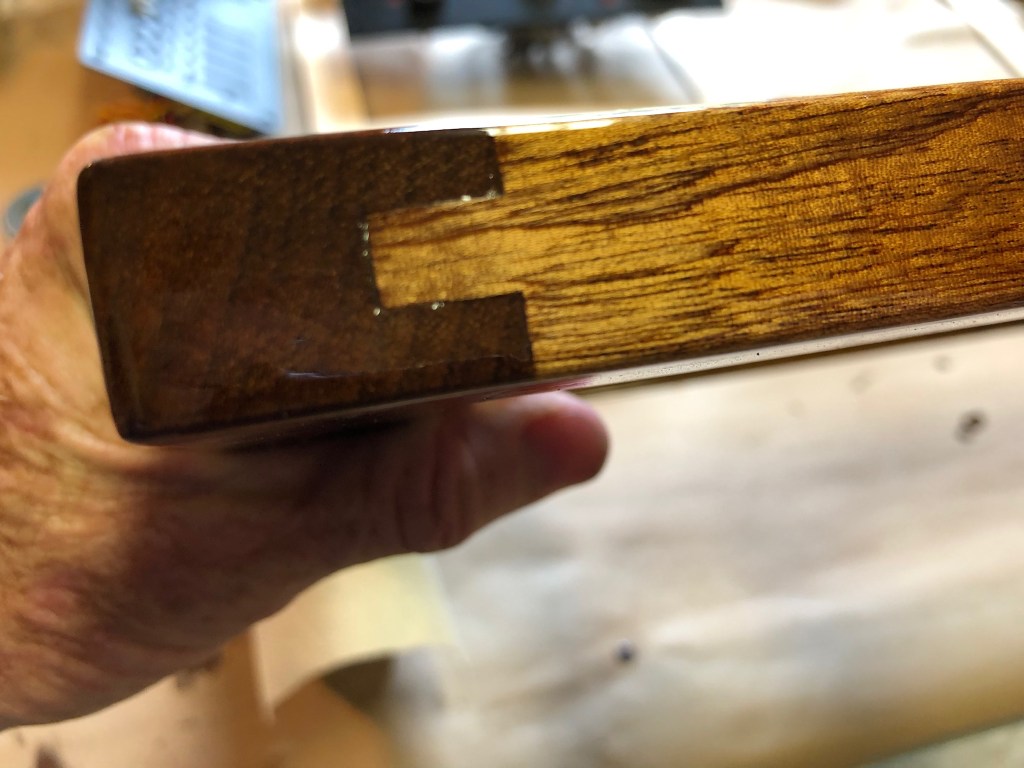
Because I sailed the Far Reach for five years without an inboard engine I had to extend the longitudinal bulkhead on the starboard side of the engine so it could serve as part of the engine box. I spent some time cutting a tongue in the bulkhead then made a matching groove in the extension framing. I laminated mahogany staving onto the 1/2″ ply and trimmed it to fit precisely. Then I varnished it to match.

Below you can see the staving on the left. On the right is the frame for the extension. The 1/2″ plywood fits into the slot on one side and the tongue I cut into the bulkhead fits into the other slot. Epoxied together it’s as strong as a one piece bulkhead.
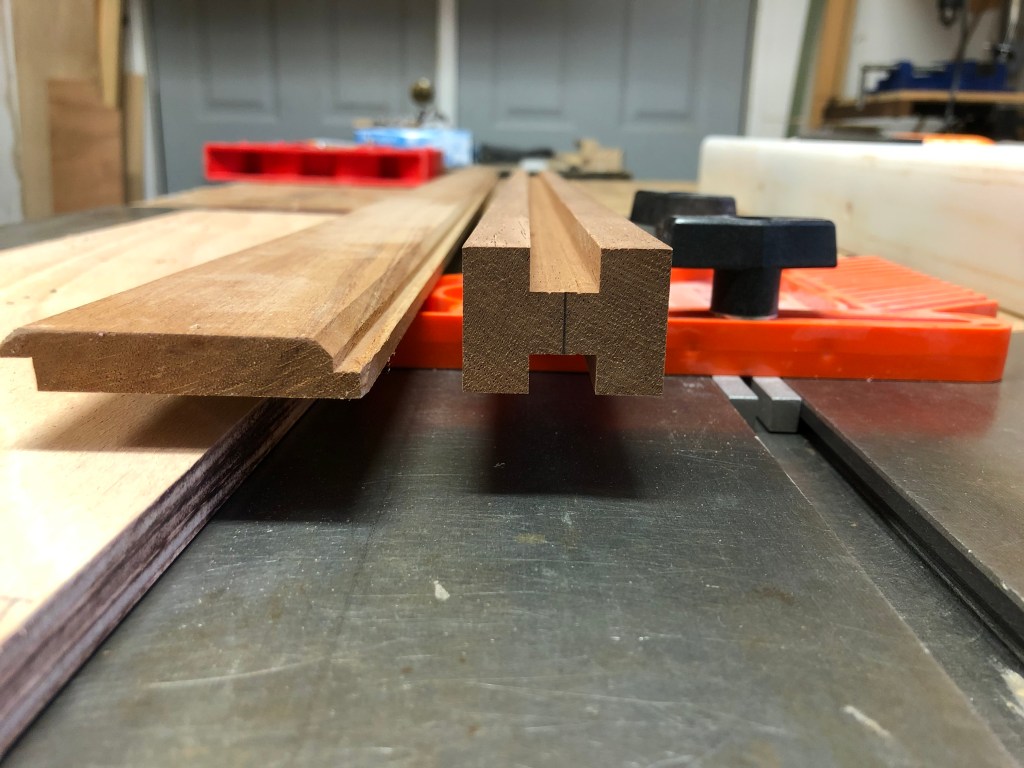


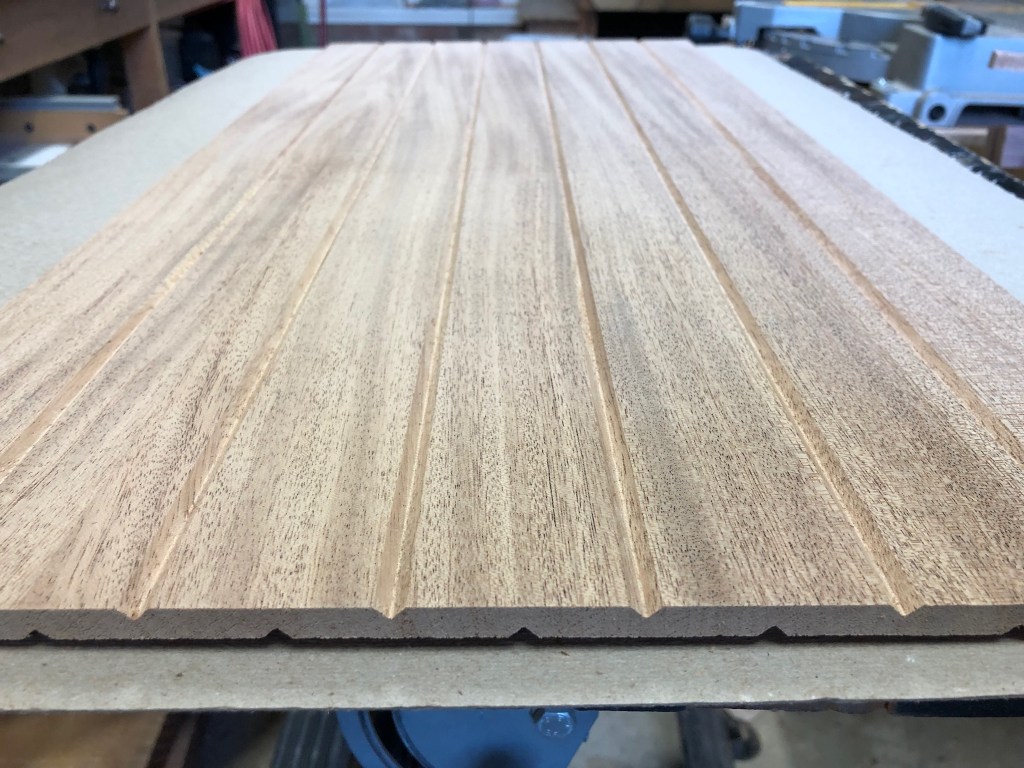
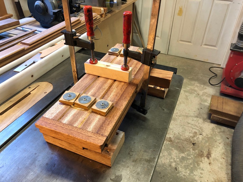
I built the bulkhead extension the same way I built all the bulkheads on the Far Reach. I milled African mahogany to 3/8″ thick then cut half laps and V grooves in them. Then, I epoxied the staving to the plywood using home made screw clamps. After removing the screws, I counter bored them and installed wood plugs. In the picture below you can see the dado I cut in the frame on two sides that fit into the tongues on the bulkhead. Epoxied in place it is as strong as the original bulkhead.
Below you can see a section of the bulkhead I made back during the rebuild after I gutted the boat. I had to cut this angled section out to install the new section. It’s a good look at how the staving fits together and forms a solid bulkhead. There are 1/32″ gaps where the staving fits together behind the V grooves so there is a place for excess epoxy to flow into when you clamp them.


With the electrical panel and engine box extension completed it was time to start rerouting wires from the location of the old panel to the new panel.

I wanted the wires to be protected but accessible. I spent the time to label the wires and protect the labeling with clear heat shrink.
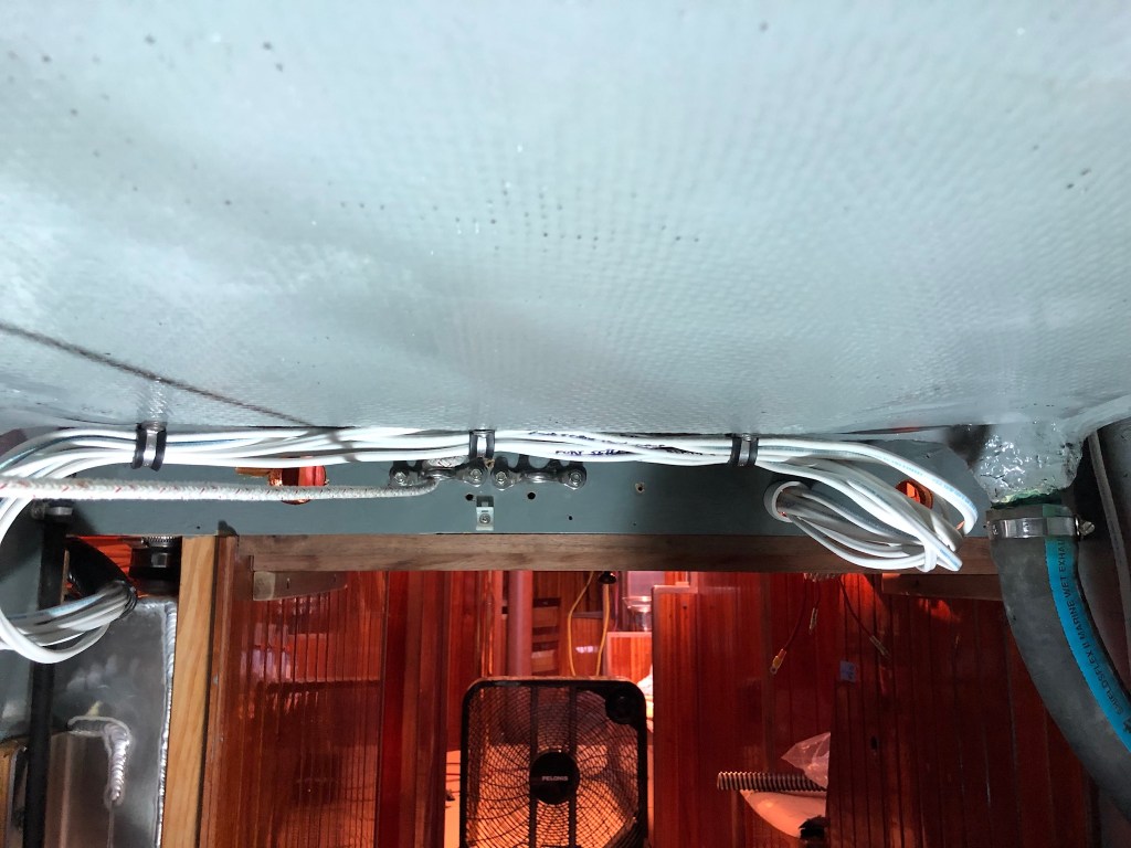

I used a single negative buss bar in the center and matching terminal strips on either side to cut down on the wiring. Wiring the panel is pleasant work. I have two mentors who are experts in different areas who have guided me for years throughout the rebuild and beyond. Having mentors is critical to getting things right. Doesn’t matter if it’s leadership challenges in the Marines, raising your kids, building a house, or building a boat. Having someone you trust to answer questions, guide you, make recommendations, or just nod that you are on target is essential to confident skill development. It’s a lot like apprenticing but it’s voluntary by both parties. Skills and philosophy are passed down. When you get the right mentors you can avoid a lot of needless mistakes. True mentorship creates a special bond. I may have rebuild and upgraded the Far Reach by myself but whenever I am onboard I can see the fingerprints of my mentors all over the the boat. It just makes me smile.
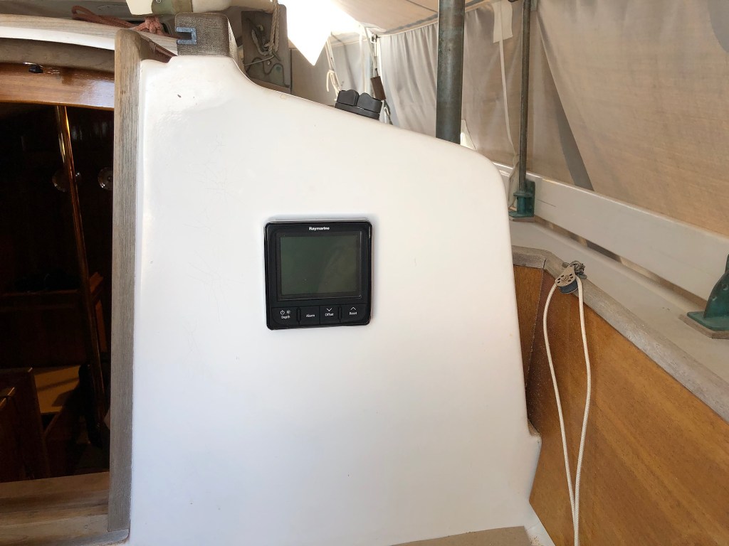
It took a long time to get to the point where I was ready to add a depth sounder. I have enjoyed “swinging the lead” and I will continue to use the sounding line because it connects me to those who went before. But, with the installation of an inboard engine I knew it made sense to add a sounder. I researched for the right one–reliable, accurate, and supports the transducer being mounted inside the hull to shoot through the fiberglass as I did not want any holes in the hull. I chose a Raymarine i50.

It took a while to figure out how to route and hide the wires yet have everything accessible.

Then of course there is always going to be varnishing.

As part of the electrical panel upgrade and along with the depth sounder I installed LED running lights. I loved having the kerosene running lights. They performed wonderfully for five years. They were bright, easy to maintain, and utterly reliable. They allowed me to keep the Far Reach simple. There is some controversy if they meet the USCG regulations. Some people say no. I say they do–without exception. USCG Navigation Rules and Regulations, Annex I, paragraph 11. “Intensity of non-electric lights. Non-electric lights shall so far as practicable comply with the minimum intensities, as specified in the table given in section 8 of this annex.” Nowhere in the regulations does it say my boat has to have an engine. And, without an engine I had no reliable way to power electric lights. So, non-electric (kerosene) was the best way for me to comply with the COLREGs. But, now that I am adding an engine, my argument is not on as strong a foundation. And truth be told, my boat while still simple by any standards, could easily incorporate lights and a depth sounder now that I was adding an inboard engine.
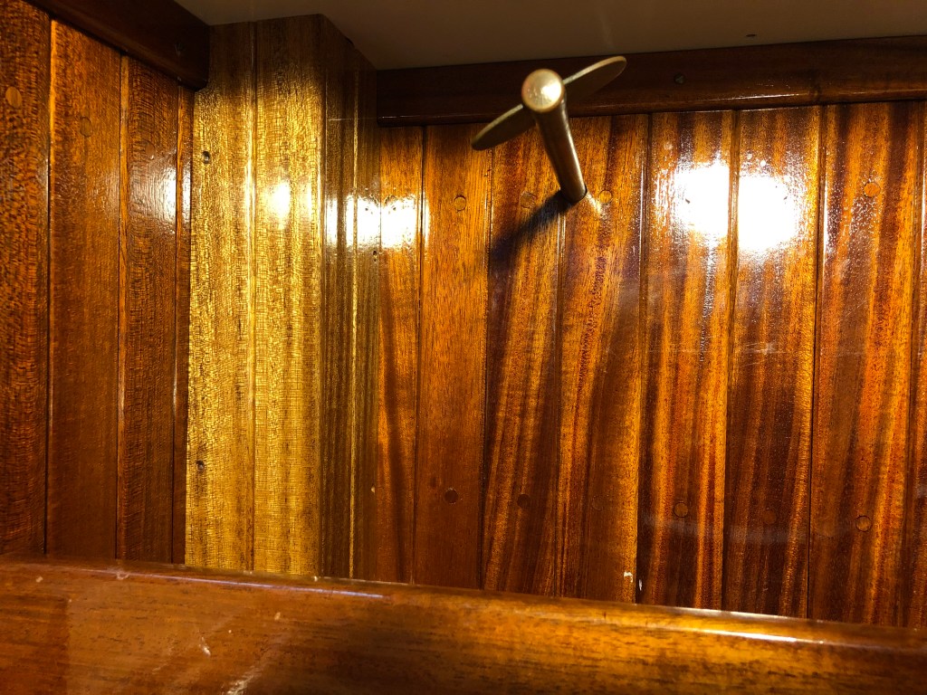
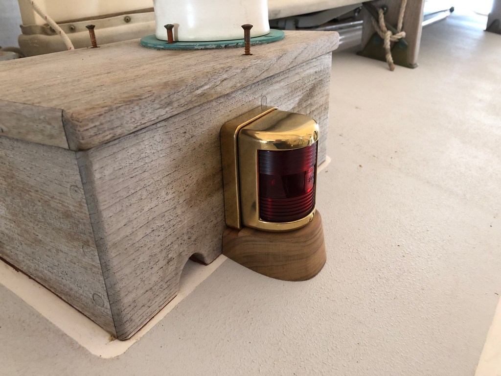
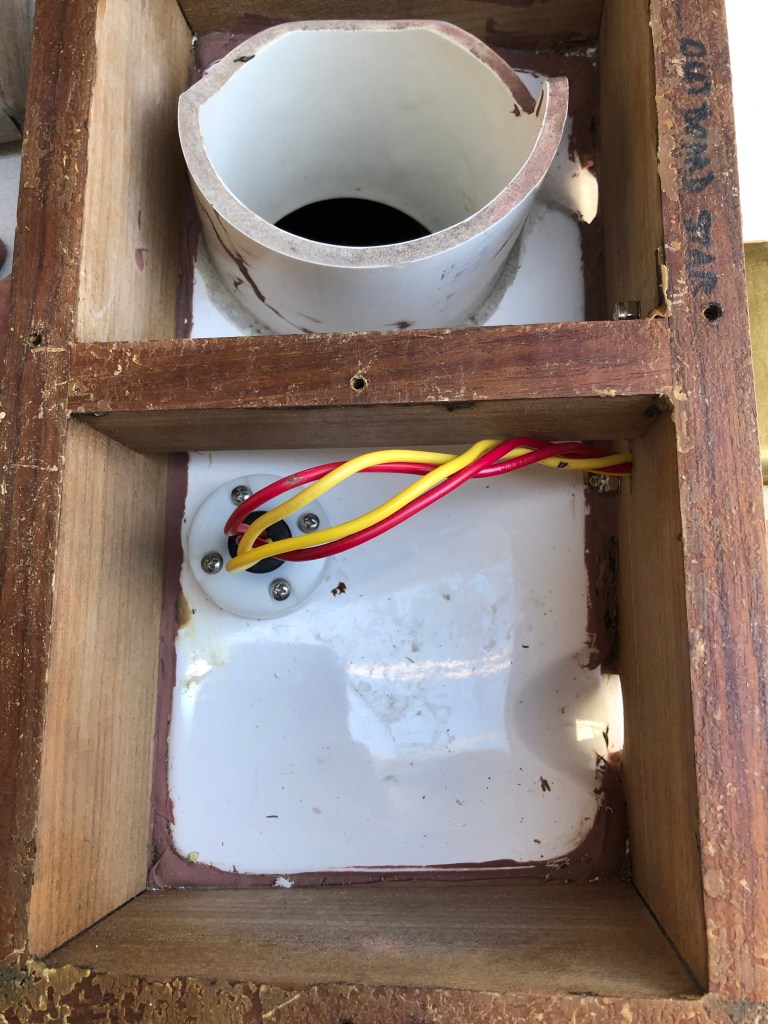
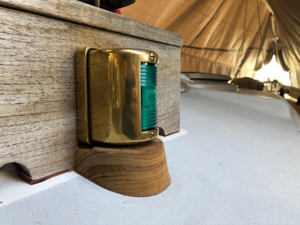
While the decision to add the LED nav lights was not simple or easy, I eventually got there and began looking for lights that would fit the style, layout, and philosophy for the Far Reach. My friend Kaj Jakobsen recommended the same lights he installed on his gorgeous self-built Lyle Hess 34′ Falmouth cutter Astrid. They are brass and are easily converted to LED. After lots of thinking (we are talking months here) I decided the best place was on the dorade boxes. The visibility was fairly unrestricted. They were protected. And, I could run the wires into the dorade and through a compression gland then back through the overhead and to the electrical panel. There would be double protection from water ingress.
Because the deck has camber, I built a small teak base under the light so lines and sheets could not get caught under it. I raised the light about 1/8″ above the base so water could drain away.
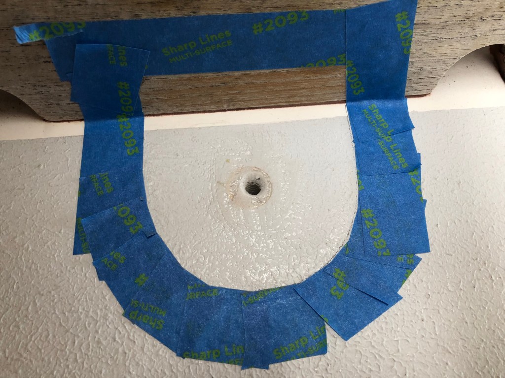
I drilled down through the base and into the deck. Then over drilled the hole and filled with epoxy. Next, I tapped the hole for a bronze machine screw. Finally, I bedded the base with teak colored polysulfide. This is a blind hole–it does not go all the way through the deck. So water can’t get into the boat or the cored deck.
I used a Blue Seas compression clamshell to run the wires through the overhead. I removed the overhead panels and ran the wiring back to the electrical panel.

The companionway ladder I built for the boat during the six year rebuild worked beautifully. But, it would not work with an engine installed because the engine would be in the way. I developed a design where the work bench would be extended forward and the ladder cut down with the top step rails landing on the work bench. Then, the vertical panel I would need to build to cover the front of the engine would have a step integrated into it. Lastly, there would be a hinged bottom step allowing quick and easy access to the raw water seacock. Cutting up the ladder I so painstakingly built six years ago was not easy, though it was necessary. Boats that live long healthy lives, like the humans that love them, sometimes have to endure changes to adapt to new circumstances. I had a great time designing and building it back in 2014 and it performed wonderfully. But there was no way around it. I took some satisfaction knowing I was still using part of the ladder in the new design. So cut it down I did.
I used a hand saw to cut the teak steps out (to be repurposed elsewhere) then made the final cuts with the chop saw.
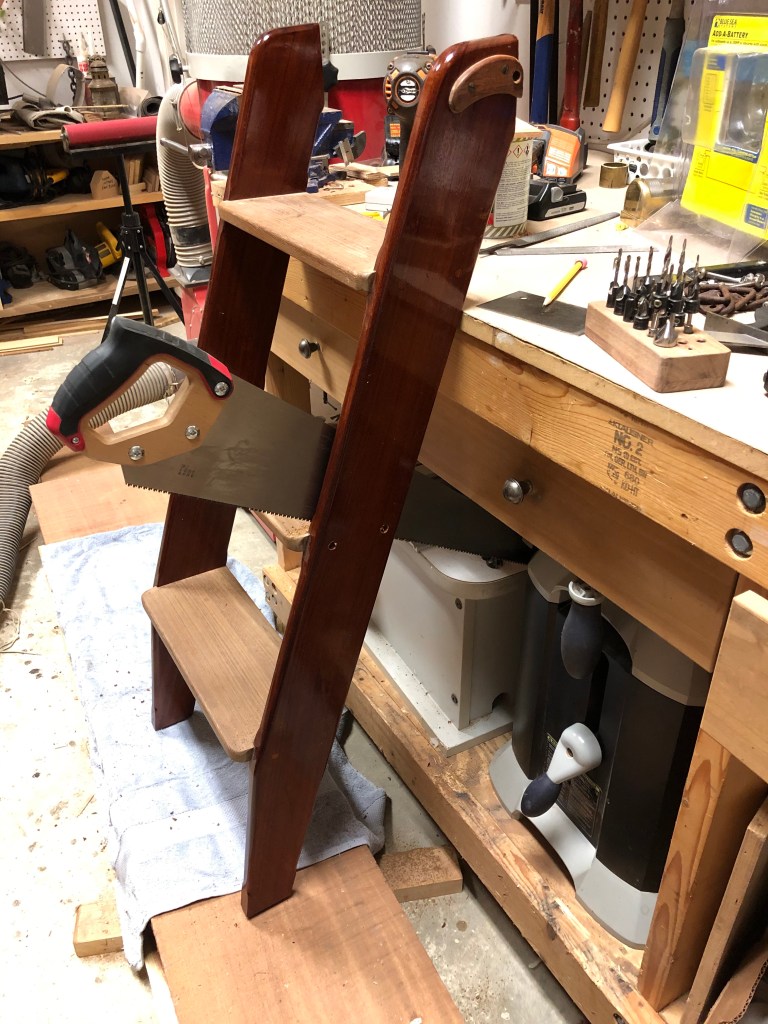
The bottom is to the left. The top of the ladder is to the right. I needed to use the old top since it fits into the snap hinges already installed on the boat, but I needed to taper the legs, like the old bottom, so the ladder has a refined, vice blocky look.

I crafted a template and made the rough taper cuts with a my Bosh jig saw then used the template and a router with a straight bit and guide bearing to make the final cuts. I removed all the varnish with a heat gun and scraper and applied seven new coats.

The ladder worked just fine.

So, this post completes the installation of the 12v panel and some of the supporting systems. It also covers some of the wood work necessary to accommodate the inboard engine with the new offset propeller shaft. The installation of the engine, shaft, engine components, and final cabinet work for the engine box will be covered in the next post.
Below is a sketch depiction of what the engine installation design looks like. I made this sketch before I ever started on the project. As you can see, I am sticking to it pretty closely.

And to serve as a teaser…in late Sept 2020 I went to the US Beta distributor just up the road in Oriental, NC and picked up my engine they had kindly stored for me for about 8 months.
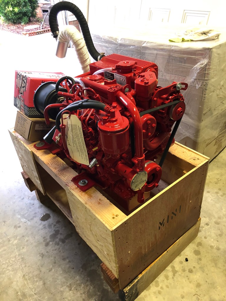
To be continued in Part IV.

Less is truly more. When you start running guns or extract assets in the dead of night, please let me know…
LikeLike
Truly artistic work backed by solid engineering. S/F Col Stone. V/R George Betar
LikeLike
“….whenever I am onboard I can see the fingerprints of my mentors all over the the boat. It just makes me smile.”
-very nice.
LikeLiked by 1 person
Thanks man. Glad you liked it.
LikeLike