

This is part IV and the conclusion of the engine installation project.
This post covers installing the inboard engine, installing the fuel system, aligning the shaft, building and installing battery boxes and the batteries and cables, installing the engine throttle control head, starting and test running the engine, stripping and reapplying barrier coat and anti fouling paint, installing the two blade folding propeller and making final preparations for relaunching the Far Reach after 20 months on the hard.
Before I could install the engine or the support systems that would be located in the engine space I needed to paint the engine compartment with Interlux Bilge Kote (the same paint I used in all the bilge area of the boat). I also needed to install as many components as possible before I installed the engine while I still had relatively easy access to the engine space.
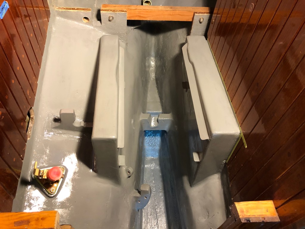
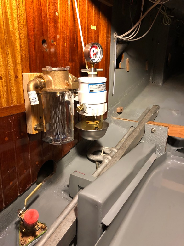
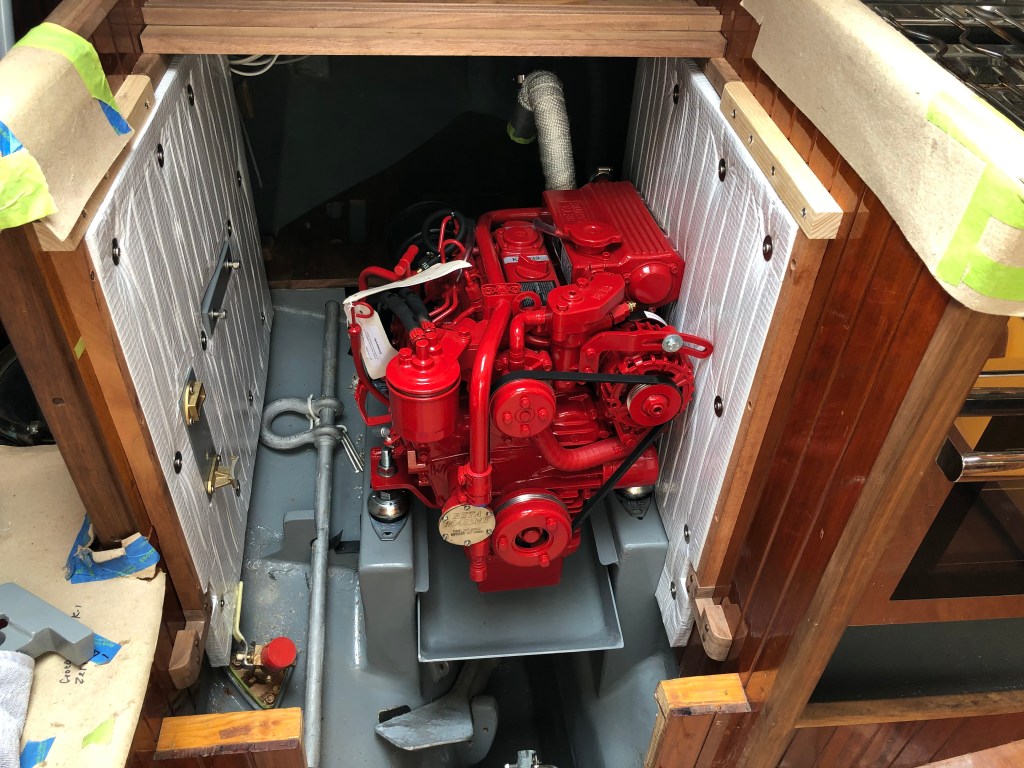
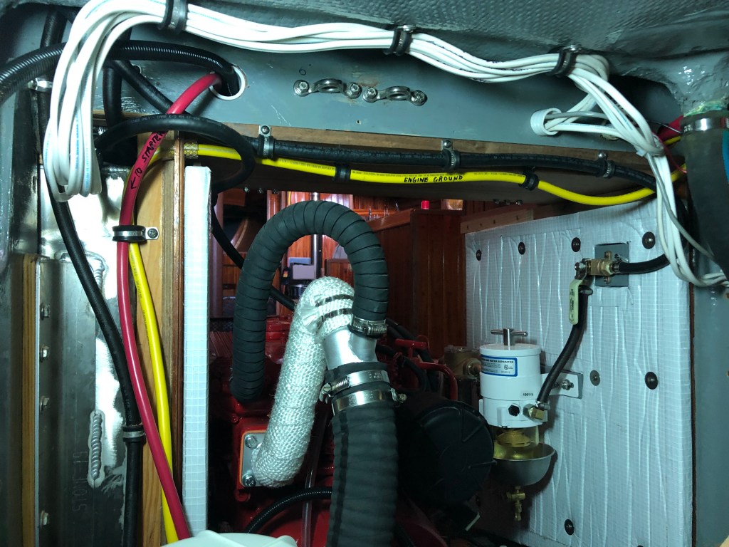
I installed the Racor fuel filter and the raw water strainer on 1″ thick wood blocks so they would be flush with the 1″ thick Sound-Down insulation. Satisfied with the set up, I used a hot glue gun and door skin ply to build templates for the engine room insulation.

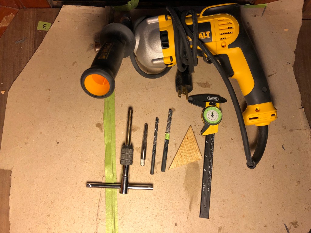
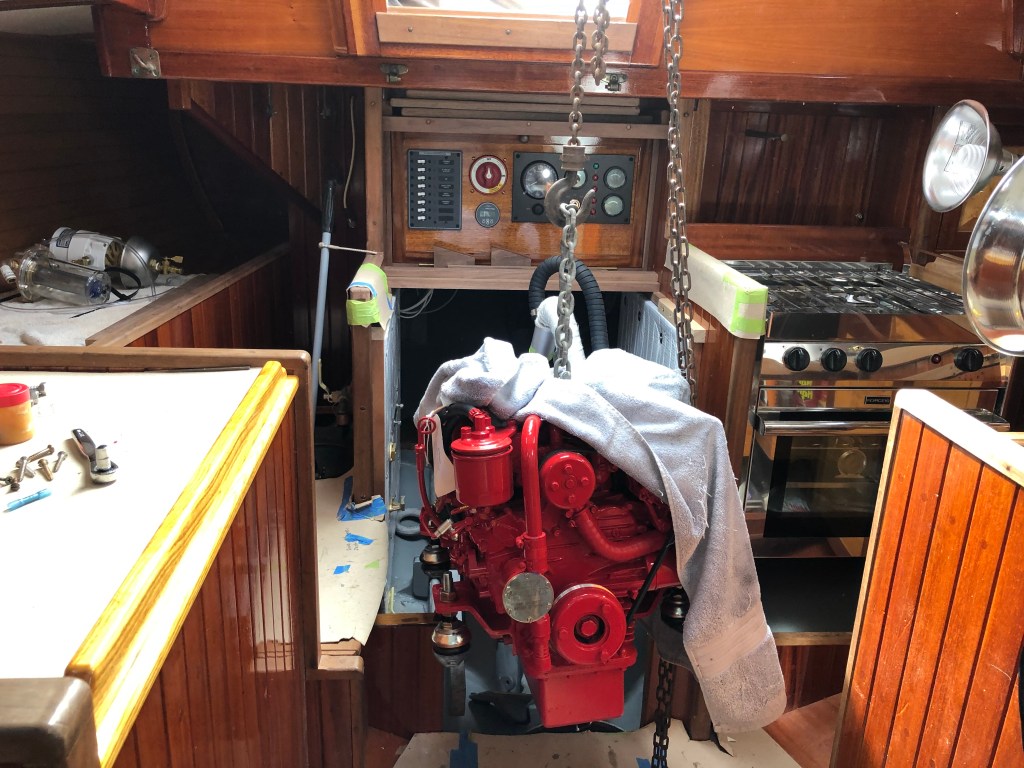
With the compartment painted and the essential insulation installed it was time to install the engine. I had gone to a lot of trouble to build an accurate engine template. I had to get it right before I drilled the hole for the shaft log and then built and install the engine beds. It would be difficult to drill holes for the feet of the engine with the engine sitting on the beds. A number of people told me to install the engine, make the feet, remove the engine, drill the holes, then reinstall the engine. That seemed like a lot of unnecessary work if the engine template was accurate. I double checked the measurements and decided I would trust the template. I felt the risk was negligible as I was confident the template was dead on. So, I reinstalled the template, ran the string and set up to drill the holes.


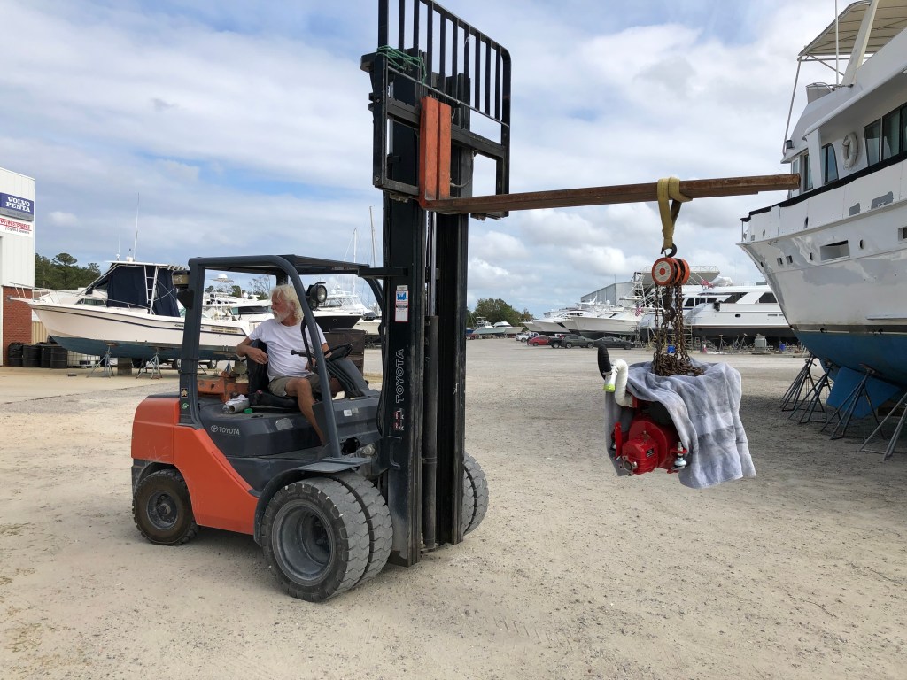
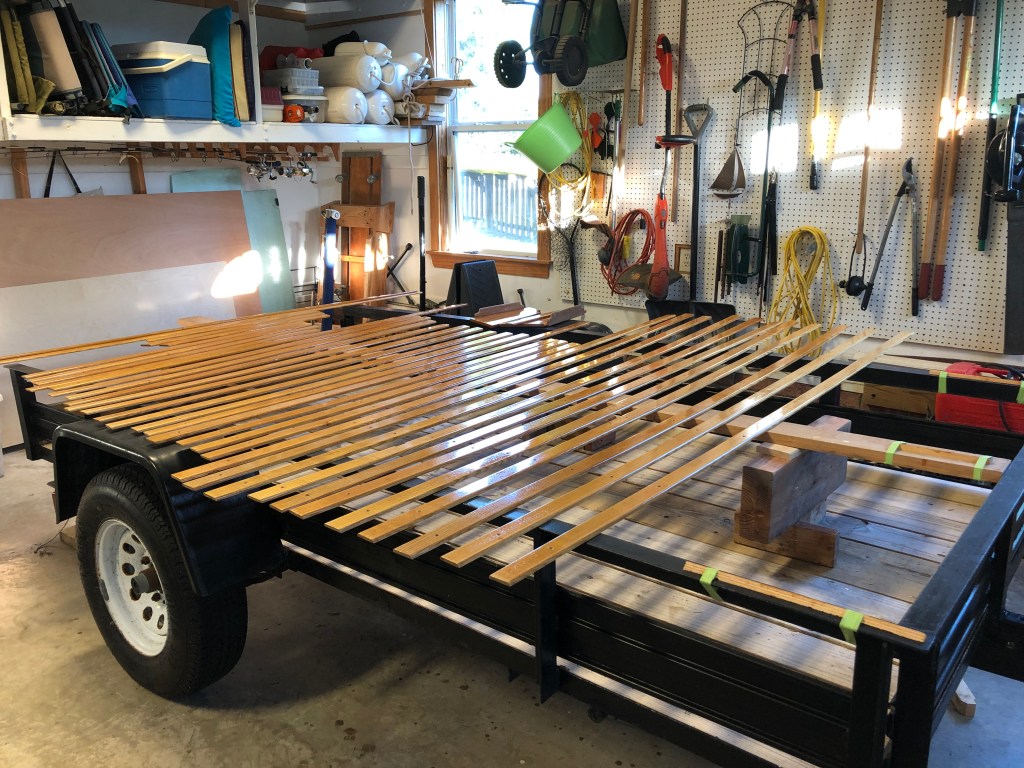
I got some help at the boatyard. They arranged a high lift fork lift and loaned me a chain fall. The two owners of the yard have been very supportive of my project and provided some muscle and extra hands when it was time to install the engine.

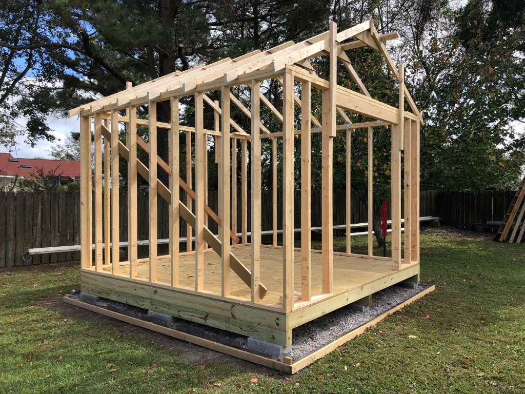
I had to stop work on the boat for about a month. Gayle and I had long planned to build a shed in the backyard. So we tackled it through most of Oct 2020 while the weather was good. We worked on it pretty much every day and as soon as we got it shingled and painted it rained for about three months. It was the most seasonal rain I have ever seen in eastern NC. The rain had little impact on boat work though as the boat was was under cover and everything I needed to do was inside the boat.


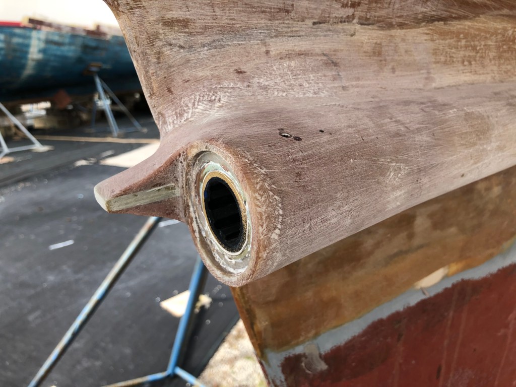
I did mange to do some fiberglass work to fair in the shaft log in a more streamlined manner as well as install the shaft bearing.
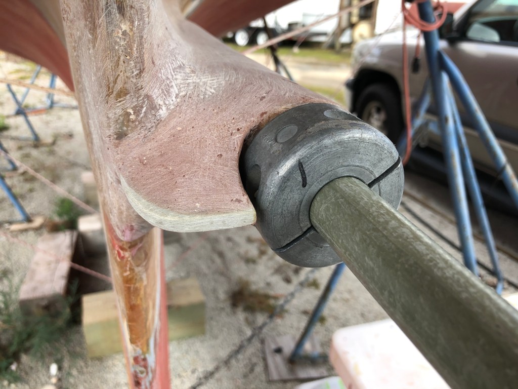

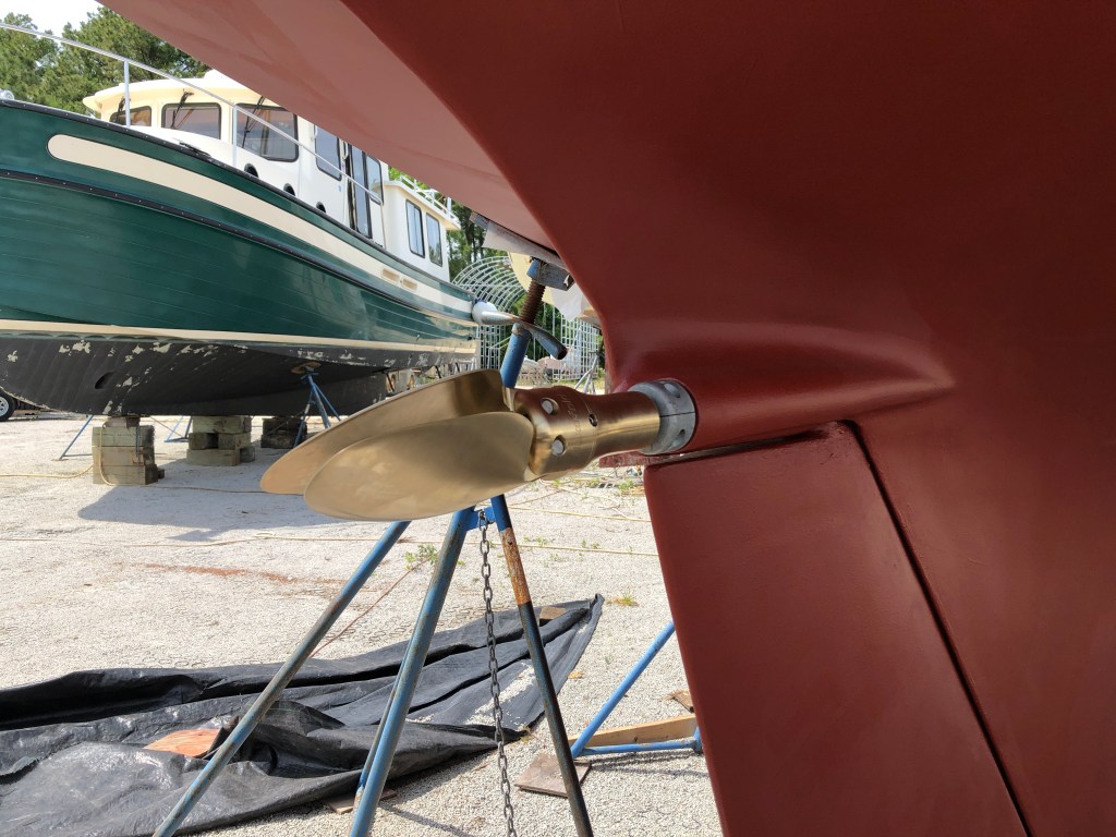
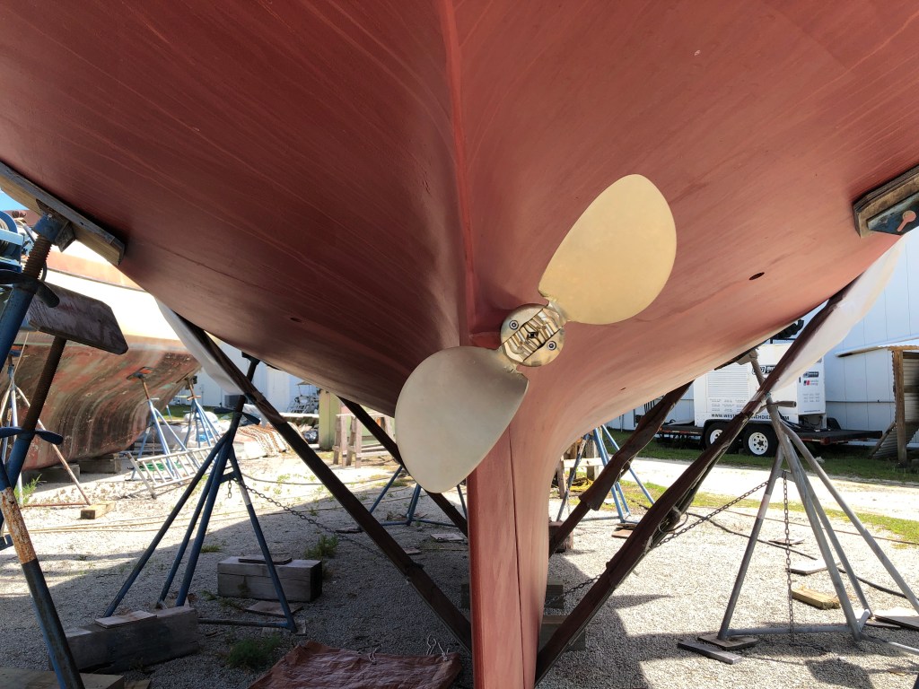
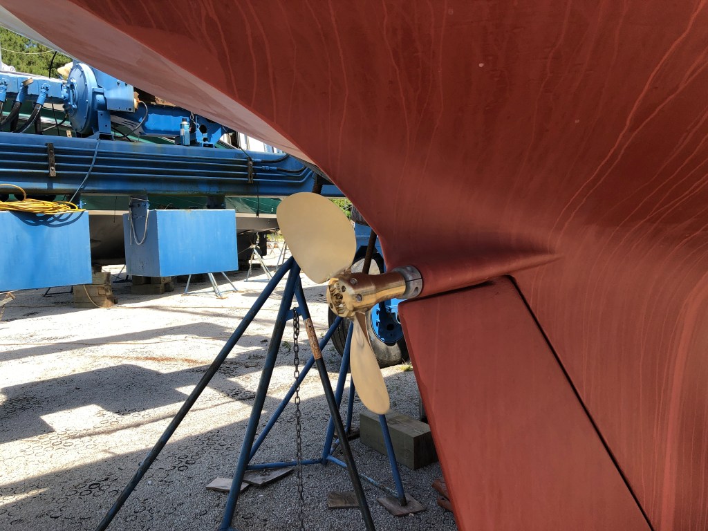
With the shaft installed I test fit the Flex O Fold 16x 12 two blade folding propeller.


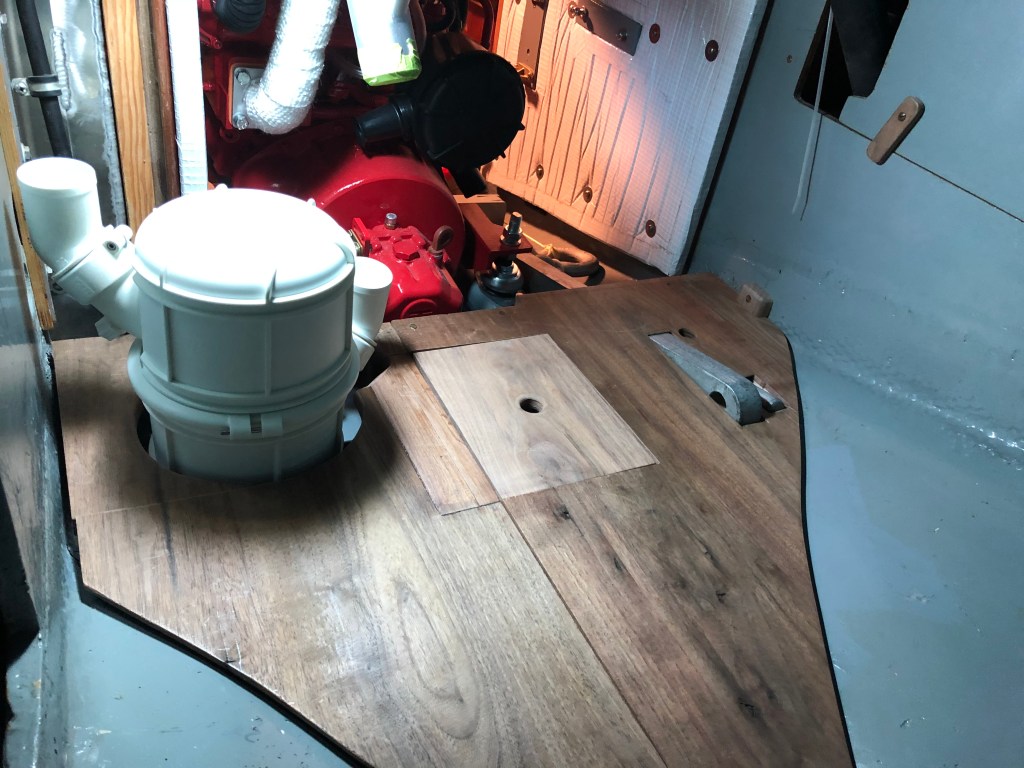
I was working on a couple of projects at the same time. I needed to build a platform for the waterlock muffler. It took a while to figure it out. After looking at different mufflers I decided the Vetus round muffler fit best. It is also adjustable so it gave me the most options for fitting it in a small out of the way space so I could maintain as much storage space behind the engine as possible. Another consideration to all the engine support systems was to make sure I had maximum access to the engine and its support systems for maintenance. Too many times boat yards simply don’t care or don’t have time to think about what happens when a system has to be repaired or maintained. They just shoehorn that stuff into the boat and move on to the next project.

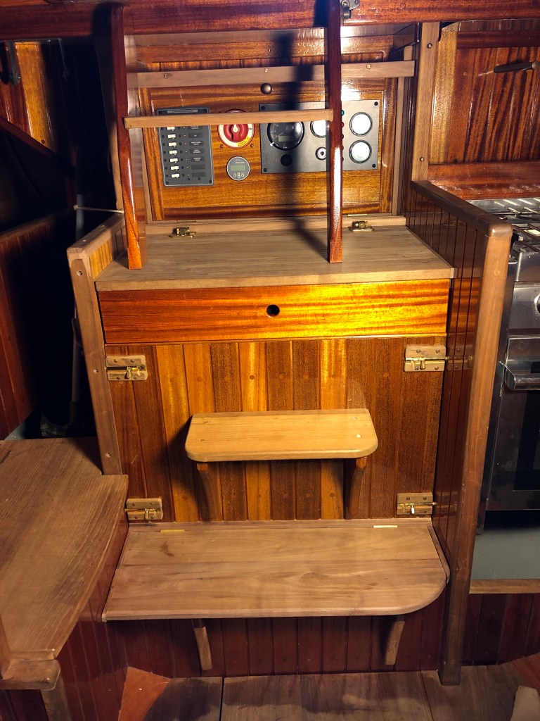
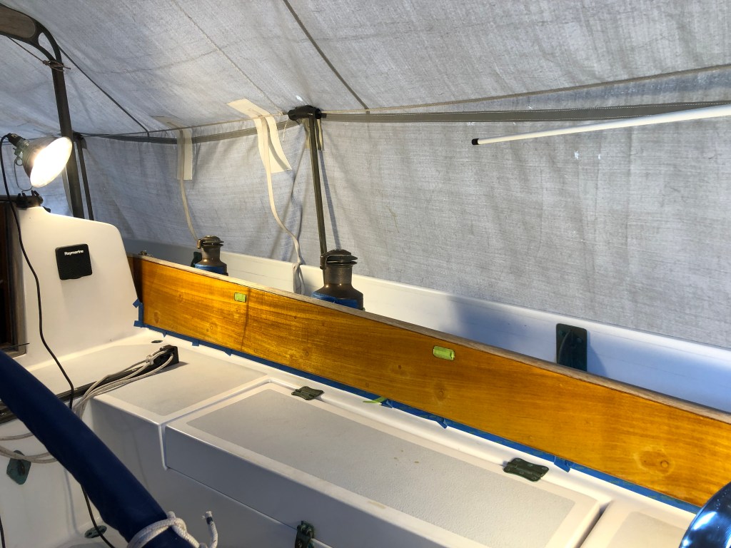
The next task was to complete the cabinet work on the engine compartment. Remember, there was no cabinetry here before I installed the engine. The engine space was entirely open for storage from the companionway ladder to to the aft side of the rudder post–almost eight feet in length. There were walnut planks that ran all the way back to the hull. The companionway ladder landed on the forward end of the planks. I retained the work bench from the original rebuild though the top is about a foot deeper since the ladder now lands on top of the work bench.
I built a template from deerskin ply then made the forward face of the cabinet the same as I made the staving for the rest of the boat. I cut a 1/2″ thick Okume BS 1088 panel to fit the space. Then I braced the back with two ash cleats which I glued and screwed to the plywood. Then I used 2″ wide mahogany staving which I milled last year for this project. I epoxied the saving to the ply and the ash bracing kept the panel flat as the epoxy cured. If you don’t brace the panel in such a manner, or epoxy staving to both sides to exert equal stress on the plywood, it will bow towards the staving. The epoxy shrinks a little as it curves. If you brace it, it will cure flat. Which it did.
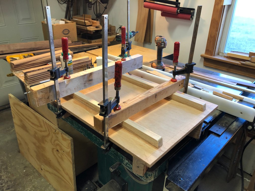
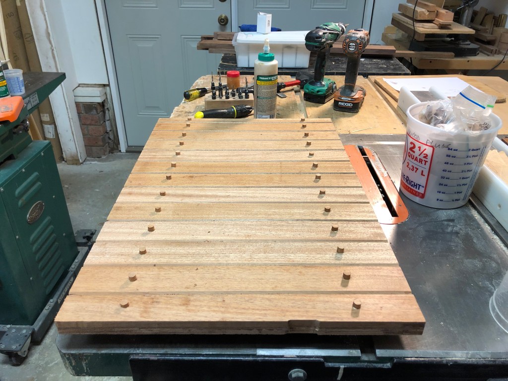
After the panel cured I installed wood plugs and took it to the boat to test fit. It required only minor trimming to fit perfectly.

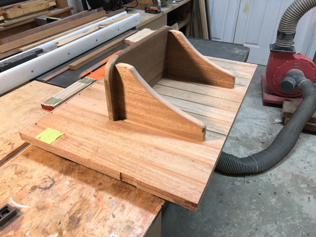
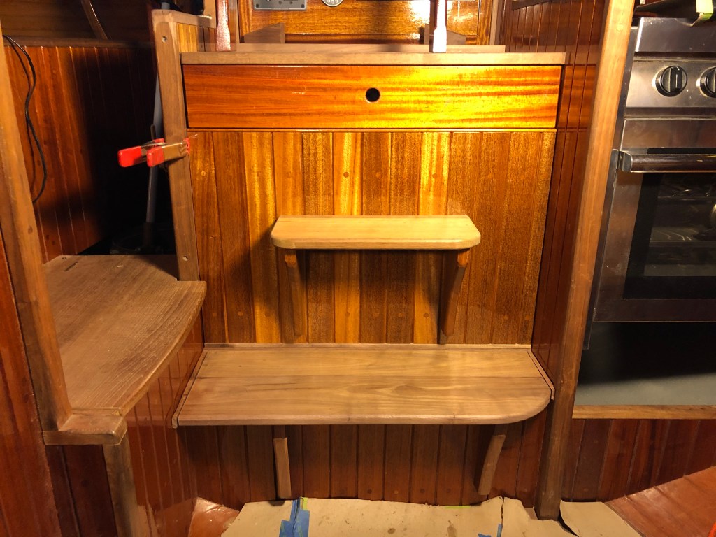
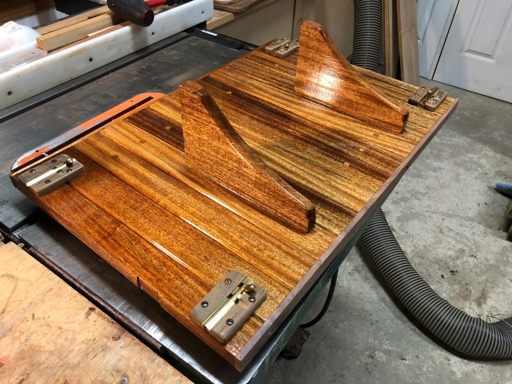
Satisfied how it fit I took the panel back home and built a step to be attached to the face of the panel supported by two gussets. I glued and screwed the gussets to the panel but I wanted to be able to remove the step so I secured the teak step (which I repurposed from the companionway ladder I cut down earlier) with four bronze flathead screws.
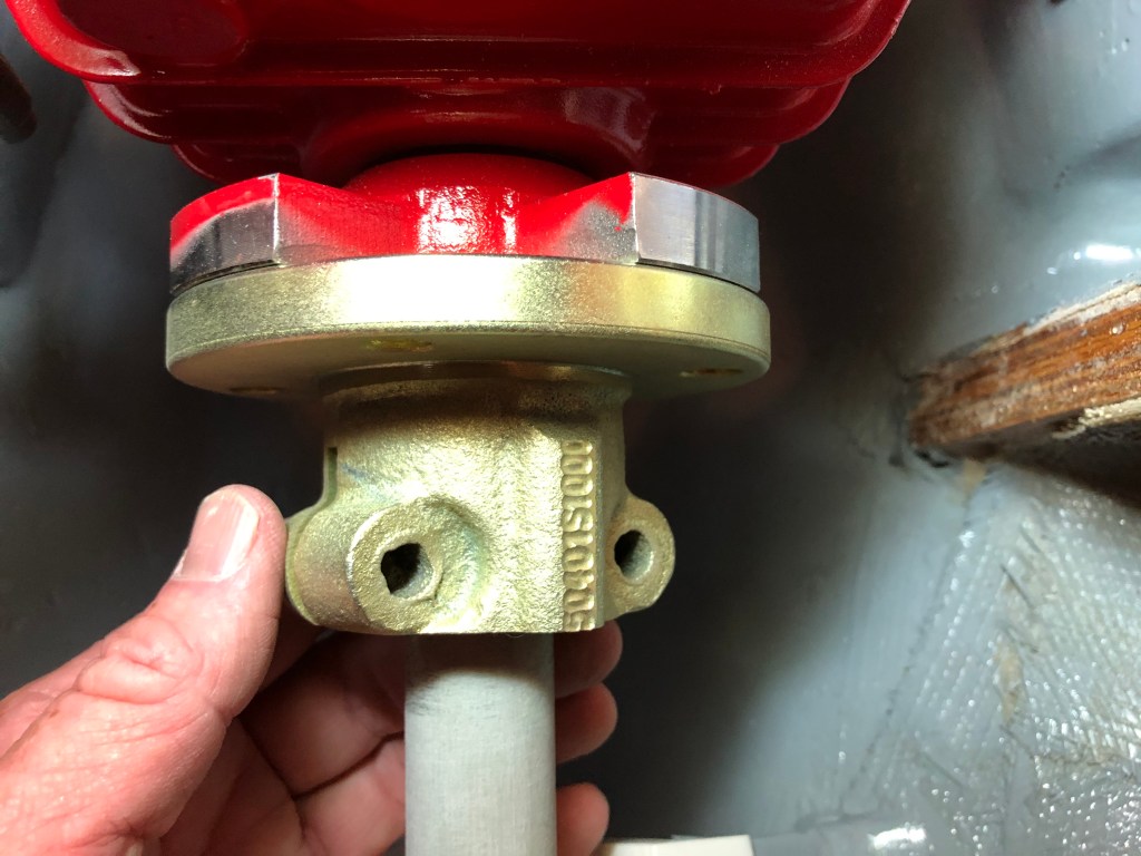
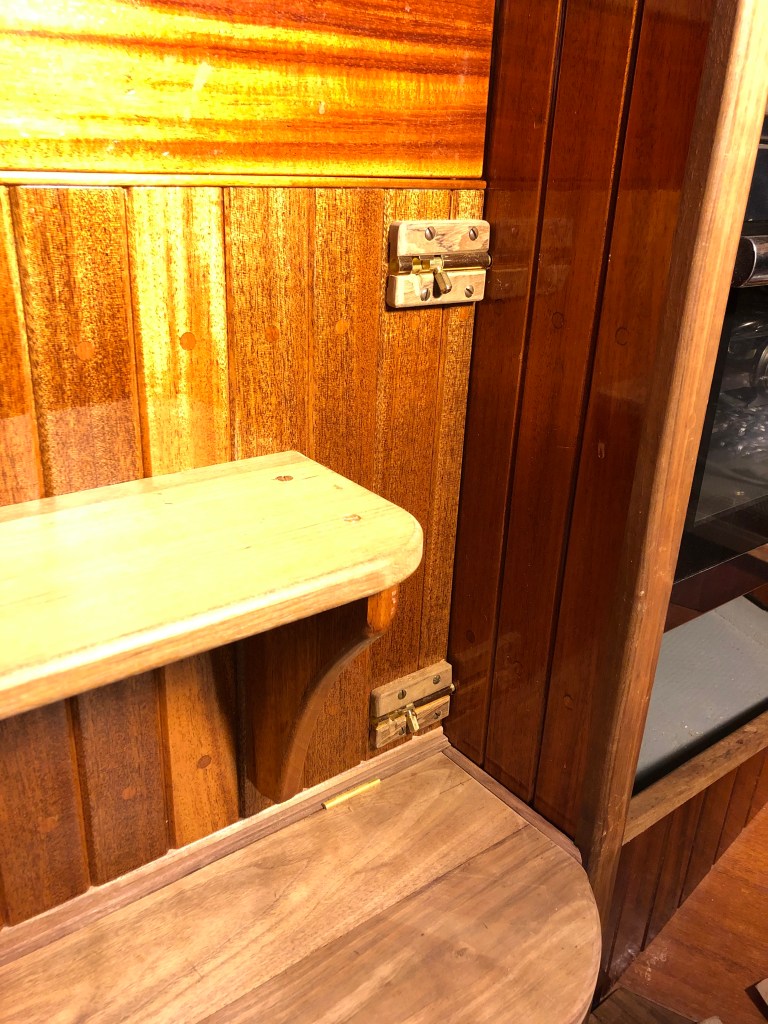
Next, I went about designing and building a hinged lower walnut step which allows access to the engine raw water seacock. It’s also supported by gussets secured to the bottom removable step riser. It’s simple and quick to remove all this cabinetry and get access to the removable drip tray or the storage space under it as well as to the engine. The walnut and teak are bare while the mahogany has seven coats of varnish. Same as the rest of the staving and cabinetry in the boat.
I needed to install a bracket system to secure the removable riser under the bottom step. I wanted it to be able to easily lift out but also be secure. I decided to install bronze alignment pins for the bottom edge and then made some slot tabs from ipe iron wood scraps and 1/4′ silicon bronze scraps I had on hand from other projects.


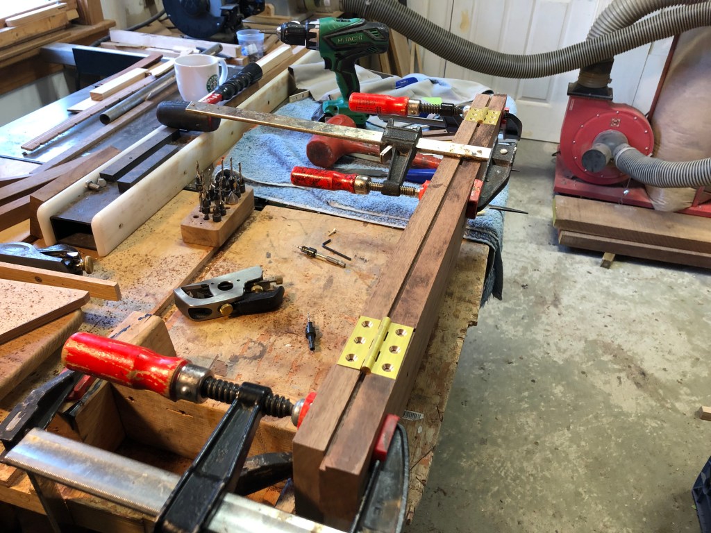
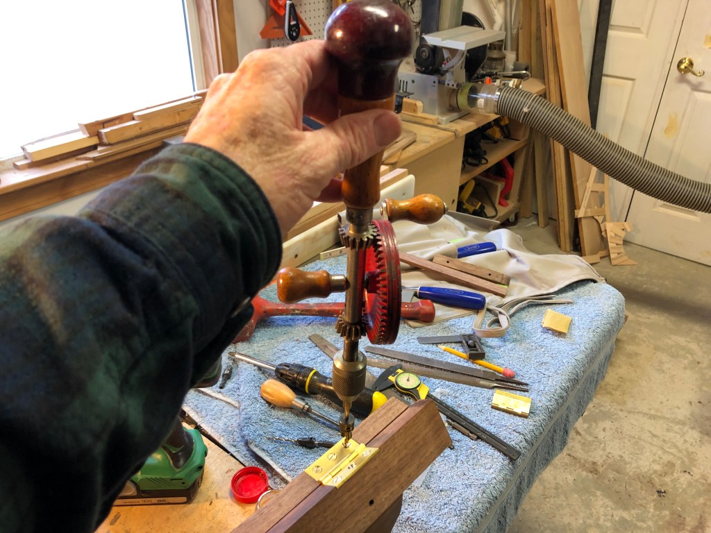
After test fitting the various parts of the removable engine box I was ready to install the brass butt hinges for the bottom step. I purchase these from White Chapel Hardware. They are beautifully made solid brass extruded hinges. They are also very affordable. They are the same hinges I used throughout the boat for all the cabinet doors.


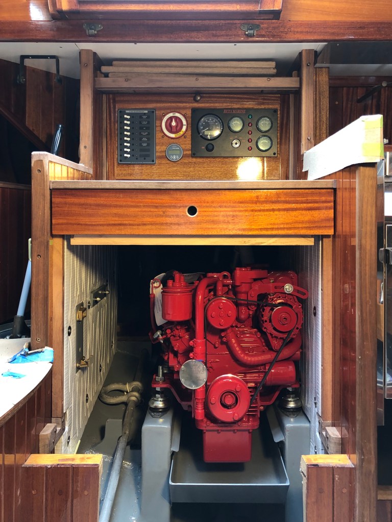
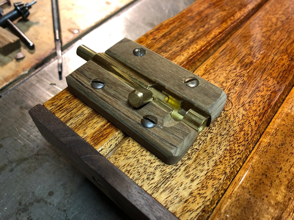
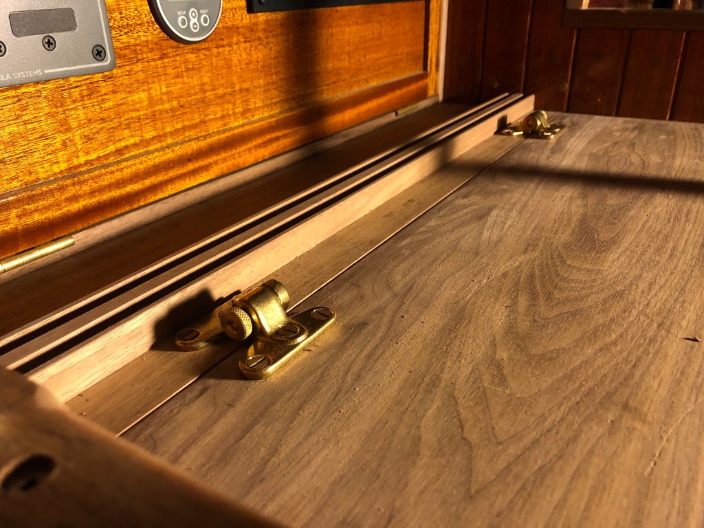
I spent a lot of time thinking about how to secure the panel in place. It has a step integrated into it and that’s the step I like to stand on with my arms on top of the companion way sliding hatch rails. So, the panel needed to be very secure. I decided to use four solid brass sliding bolts. I also decided to cover the flange part of the brass bolt with teak. I thought it gave it a better more handcrafted look. I also thought it would be stronger. I left the teak bare because your hands are always on them and the locking part of the bolts would likely scratch up the varnish. I reasoned the bare teak would be durable. They work very well. The four brass bolts, even masked a bit by the teak still look a little more “busy” than I like. If I had spent more time on it I might have come up with a way to secure the panel without any bolts or locking mechanism visible on the front of the panel. If I figure out how to do that in a simple robust way I might change it at some point in the future. But, I am happy with it and I do think it looks pretty good. I’m still learning….

Next, I installed brass snap apart hinges on the work bench top. I used these same kind of hinges on the removable companionway ladder. I like them. They are strong and work well. The snap apart hinges allow me to either rotate the work bench top up for easy access to the engine because they function like a hinge or remove the work bench top completely for maximum access to the engine as they quickly snap apart.

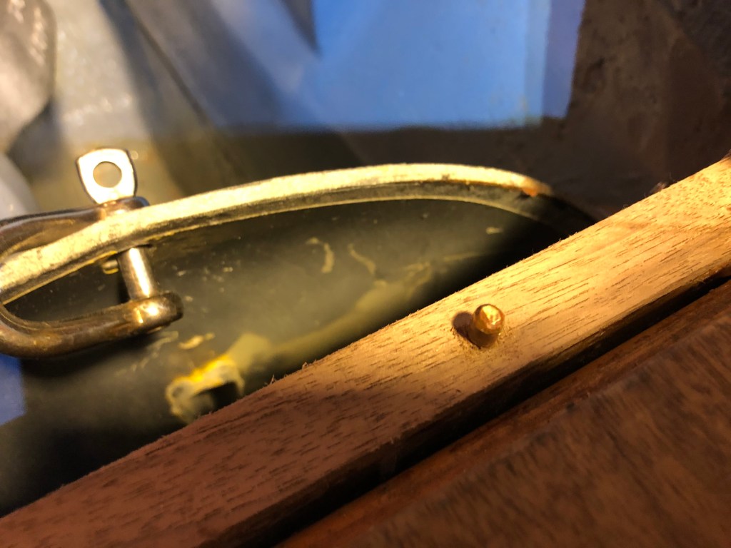
With the work bench secured in place I installed bronze alignment pins in the bottom legs of the ladder that rests on top of the bench. I installed them the same way I installed them under the bottom step riser. I drilled holes and screwed #12 round head bronze screws into the wood. I bury the screw to the riser but no further. Then, I remove the screw and hack saw it off and file it smooth. Then, I reinstall the screw with vise grips. Sometimes, if I have good access, I can cut the head off with a Dremel and file smooth without unscrewing them.

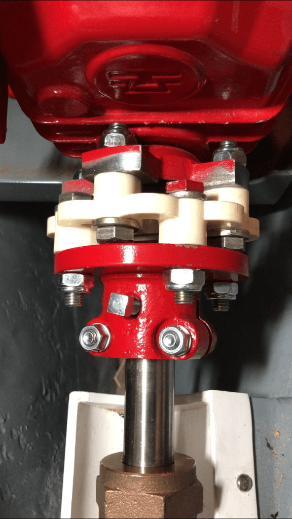
With the cabinetry essentially complete it was time to align the new SS propeller shaft. It was January and we were in a deep cold spell. Even with the boat under cover and the electric oil heater keeping the saloon warm it was cold in the space behind the engine. I spent a great deal of time sitting on the fiberglass hull because I removed the walnut floor to have better access to the prop flange.
Though the shaft was closely aligned from the original installation it needed to have a very tight fit to prevent premature wearing out of the cutlass bearing. The approach was to marry up the two flanges without the flex coupling. Then, once aligned within acceptable tolerances, install the flex coupling. It took a good long while because I had to use the feeler gauge on the shaft coupling behind the engine but then crawl out of the locker and go into the boat saloon to move the engine from the forward side. Then go back to the cockpit and crawl down through the locker and behind the engine and repeat and so on and so forth. It was slow tedious work and would have been a simple event if I had help but on that day I was a one man show. After a couple hours of crawling back and forth I could not even get a .005″ feeler gauge between the flanges with the engine feet bolted down. By the time I had the feet torqued down it was dark and I was cold. But, the task was complete.


As I mentioned earlier, these projects seldom are completed sequentially. Often I am working on several projects at the same time. Partly it is to understand how they fit together–if this, then that or that etc. Options. There is more than one way forward but every decision has consequences later on for some other project. Sometimes I have to order parts or research how to complete a step and in the mean time I will see what else I can work on. When I am not sure about something or I have nagging doubts I just don’t do it till I figure it out or some new idea comes into play. In the meantime I will work on another project.
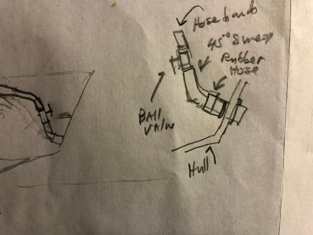
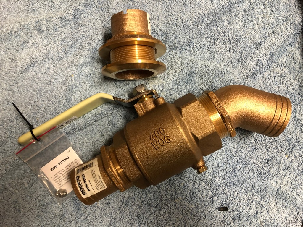
Installing the exhaust system was just such an event. If I knew exactly what steps to do before I started it would take a couple days. Instead it took about a month to install it. I was not sure the best way to do it. I had to find the right flexible 2″ exhaust hose (Vetus Slang 50) and then order a big 2″ bronze ball valve I could install in the lazarette to prevent water from being forced up into the exhaust and down into the engine when sailing offshore. That ball valve and the high loop of the exhaust had to avoid interfering with the Cape Horn Windvane control lines that run through the lazarette and lockers. I also had to think about about the engine shifter throttle control head even though I was not ready to install it. Additionally, I could not allow the exhaust hose to interfere with my having access into the space behind the engine. There were a lot of parts and steps to work out before I drilled the first hole.
The bottom line is I came up with three options and eventually by using mock ups, drawings, careful measuring, and my imagination I settled on the the best course of action.


The last project was to install the vent hose and fitting for the fuel tank. I installed it up high on the transom. I was able to keep it out of the way of the wind vane control lines and maintain max access and storage space in the lazarette. Though I had removed the original bronze Spartan Marine vents years ago I saved them and thus used one for this project.

Something that needs to be mentioned about installing a ball valve in the exhaust hose…if it’s closed and you attempt to start the engine you will cause major damage to the engine. The way to avoid forgetting to open the valve is to hang the ignition key on the ball valve lever whenever it is closed. That is the SOP on the Far Reach.
The next task was to rebuild the wood frame for the port cockpit locker. Way back during the 2009-2015 rebuild of the boat I installed a new starboard cockpit locker frame. But, I reused the port locker frame as it was repairable. it gave me no trouble for five years. However, the repairs gave way with all the crawling in and out of the locker. I picked up a couple board feet of iroko, which is the same wood I used on the starboard locker. It took a couple of days but it was a simple project and it turned out nicely. Check that off the list.


The next task was to install a bigger battery bank. For five years I sailed the Far Reach with a single 100ah Lifeline AGM and a 30 watt solar panel as the only charging source on boat the boat. It worked fine. Essentially, it was never below about 90 percent. We just didn’t have any power demands. We had no inboard engine, we used kerosene nav lights. We eventually added a couple Alpineglow interior LED lights. We charged our iPhones and occasionally a lap top. The biggest power draw was the AIS transmitter offshore and that only drew a couple amps per day.
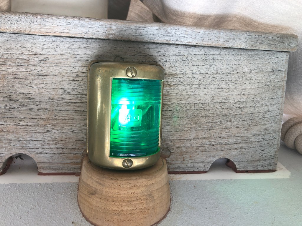
Adding an engine, however, induced me to transition to LED navigation lights. Though some folks wanted to argue my kerosene nav lights were illegal I always felt we were on solid ground with the Coast Guard.
Annex I, paragraph 11 of the USCG Navigation Rules and Regulations Handbook has a provision for “non-electric lights.” It states, to wit, “Non-electric lights shall so far as practicable comply with the minimum intensities, as specified in the table given in section 8 of the Annex.” The key issue is it has a provision for non electric lights and the key words are “so far as practicable.” But, for me, with the installation of an engine the whole rationale and justification for kerosene nav lights vanished. I had kerosene lights because without an engine I had no way to provide power to them. Now that I was installing an inboard engine it just made sense to install LED nav lights. In for a penny, in for a pound–I also decided to install a Raymarine depth sounder. I still have my lead line and I still plan to use it. It does not lie and I can sound wherever I want and not just know the depth in one spot under the boat. Nonetheless, these are all small power demands. Negligible in fact.
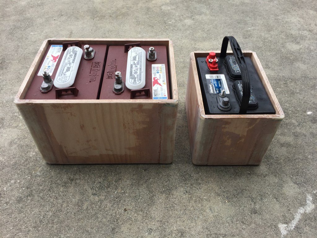
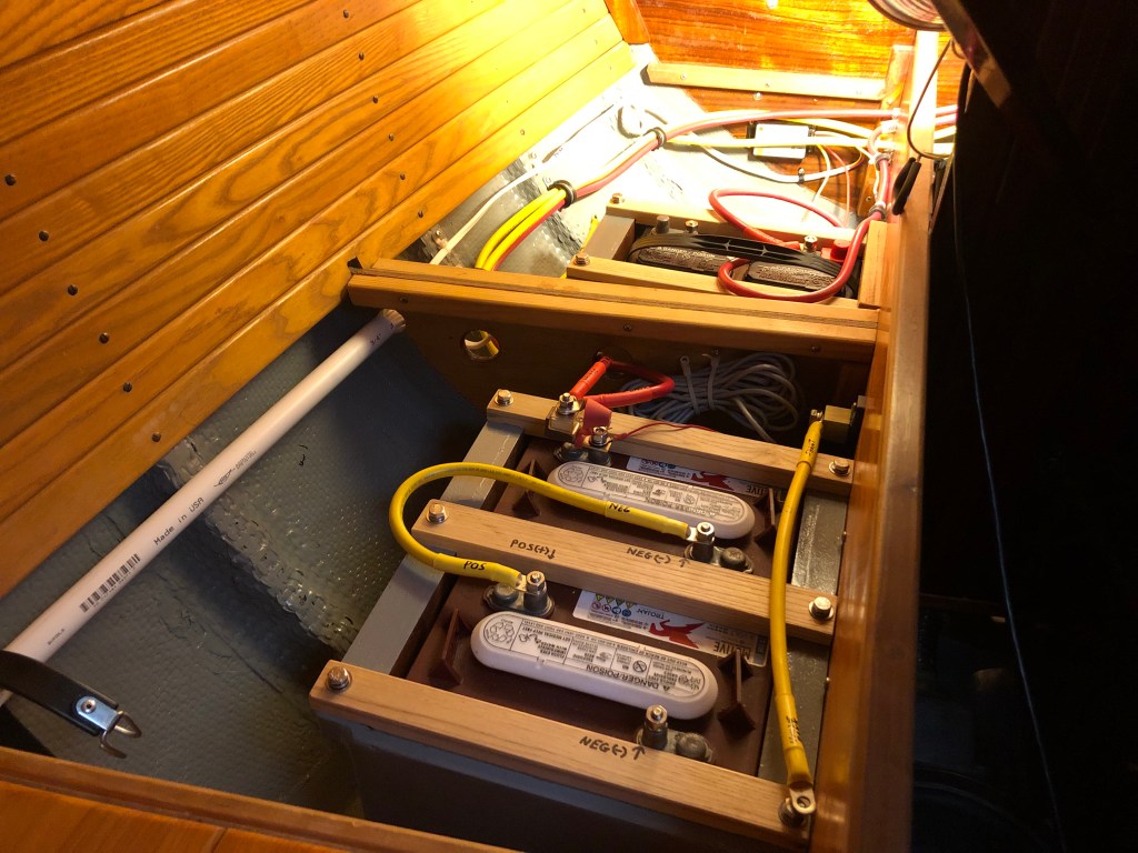
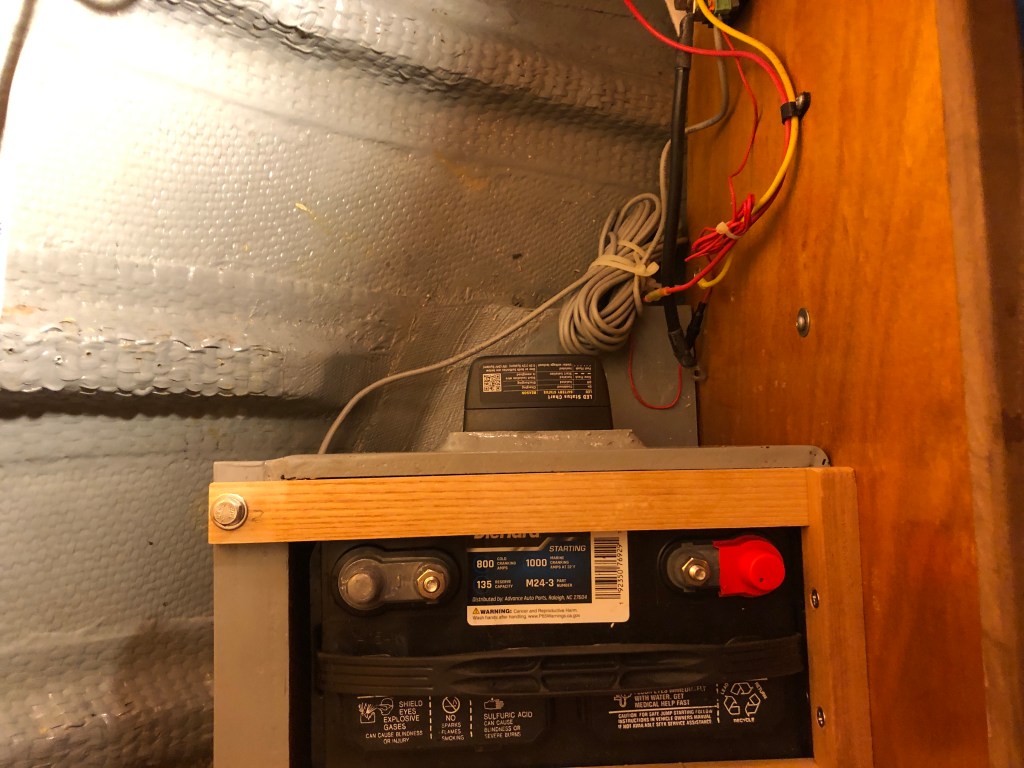
I liked the AGM battery for all the well known reasons. But to increase the bank required me to double the cost. And, if I ran the house bank off AGM then the engine battery needed to be the same. I was looking at about $1,100 minimum to do that. By going back a step to wet cell batteries I could save a lot of money. And the batteries I chose, Trojan T105s (often referred to as golf cart batteries) are the most robust and durable deep cycle wet cell battery available. They routinely last 8 to 10 years. They are 6 volt and therefore needed to be wired together in series to produce 12v but provide 225 amp hours of storage. Total cost for the Trojans was $320. I more than doubled the depth of the bank from 100ah to 225 ah for the same cost as a single 100 ah AGM. I purchased a Diehard series 850 cranking amps group 24 wet cell starting battery for the engine. Cost was $90 at Advanced auto. If it goes bad I can replace it almost anywhere in the world. This is a very simple system. Affordable, robust, reliable. No fancy smart chargers required. No technicians wearing lab coats required to troubleshoot or repair the system. We will see how it works in the long run.
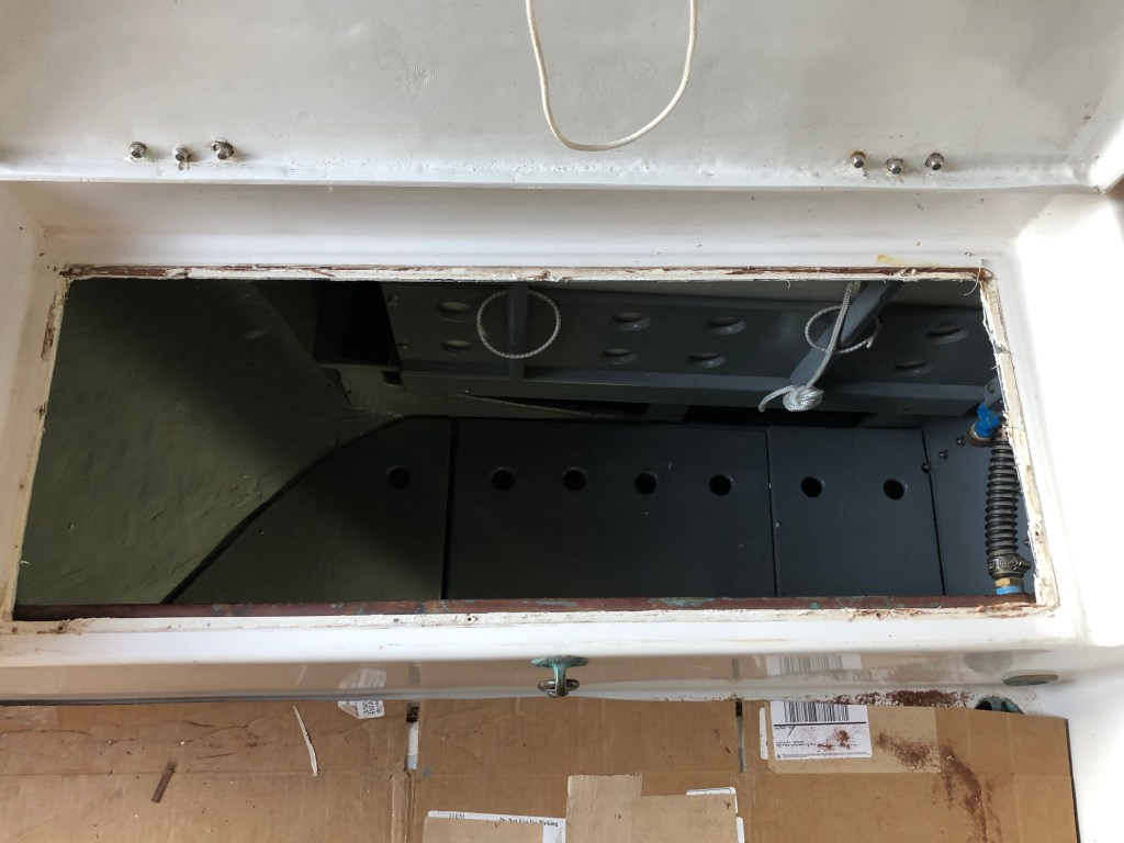
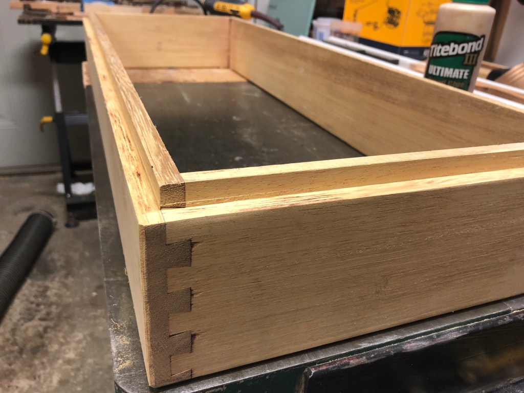
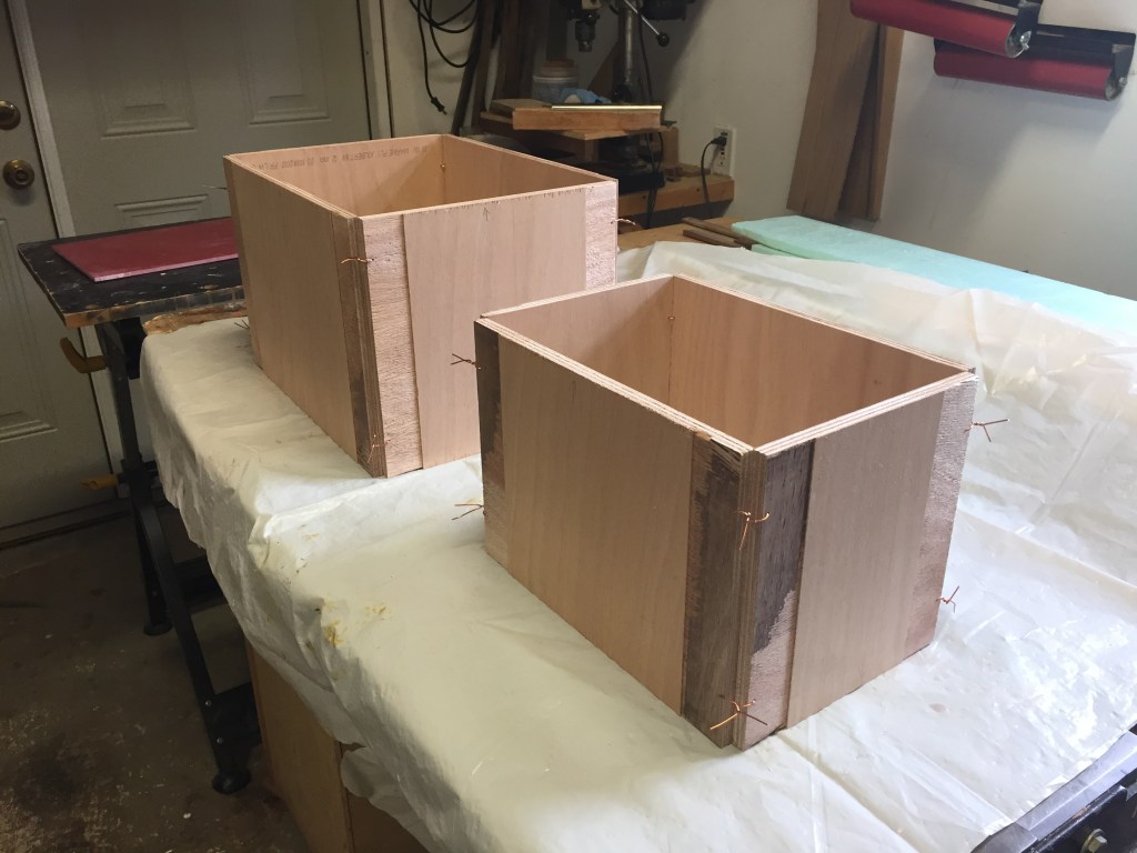
Because the batteries are wet cell I needed to build strong boxes that would secure them and contain any acid should it spill out. It would, I think, take a serious knock down to spill any acid. And, we will have much bigger problems than some spilled battery acid if we have a serious knock-down.
Anyway, after a lot of measuring I chose to install all the batteries in essentially the same spot as the old AGM–under the quarter berth. The start battery would go in the same place, under the foot of the Q berth, as the old AGM house battery. I would sacrifice about 2/3 of the middle compartment of the Q berth to the two battery Trojan house bank. I built the boxes with a solid 1/8″ manufactured fiberglass bottom and 1/2″ Ocume BS 1088 ply reinforced with strong filets of epoxy and 1708 biaxial. I built a hardwood retention system to keep the batteries in the boxes in case of a knock down or god forbid, a roll over. All the boxes are through bolted to the interior of the quarter berth.

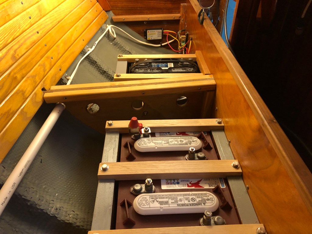
With the batteries installed it was time to wire them to the panel and to the engine. I decided to use 4 gauge wire and to follow the newish ABYC standard of red for positive and yellow for negative for 12 v systems. With a little guidance (OK a lot of guidance) from Tim Lackey, who I trust completely, I began crimping battery wires. The boatyard loaned me a big battery cable crimper and I began to measure, purchase, and run the wiring. I had to drill a few holes and epoxy the end grain and install chafing guards so it took a week or so. But it went smoothly. I ran and connected all the wires except I did not connect the negative wires to the batteries so the system was not energized.
The add-a-battery seemed a little fuzzy to me at first but once I laid it all out and looked at the wiring diagrams I understood pretty easily what was required. I decided to install the dual battery relay in the aft compartment secured to the aft face of the starting battery box. It was out of the way but accessible. Nothing to it.
Connecting the cables to the Beta engine starter and the engine ground was not easy. They were difficult to reach. I thought I was going to have to remove the starter. I called Beta Marine and we chatted about it. They said I should be able to pull the starter right out the front of the engine (remember my engine is right up against the bulkhead on the port side). But, silly me, I had forgotten I built a removable drip tray. Duh. So I removed the bottom step and the riser and pulled out the drip tray. I removed the spare anchors stored under the engine and with a little twisting my arm I was able to find the bolt on the starter solenoid. Not that difficult after all–and I did not have to remove the starter. For the engine ground I was able to use a 12″ long 1/4″ drive extension and reach it from the front of the engine. Simple, once I understood what I was looking for.
I routed the battery cables in the most direct way possible. Over the top of the engine. To the distribution panel. To the main negative bus. To the relay. To the battery switch located on the electronics and distribution panel, next to the engine instruments, under the companionway. I looked at lots of pictures and followed closely the instruction my friend and mentor Tim Lackey provided to me.


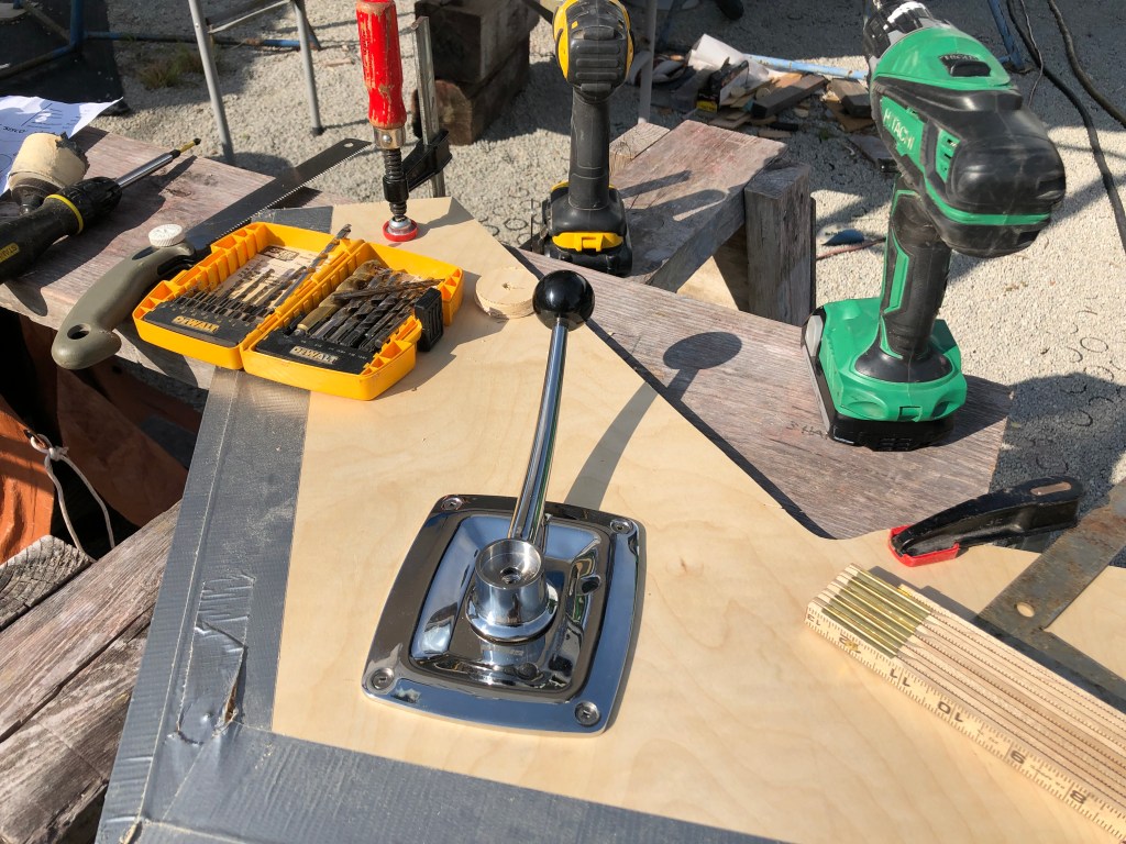
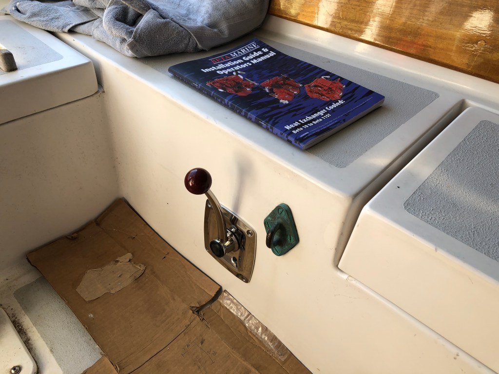
With the wiring completed it was time to install the engine throttle/shifter control. I chose the Vetus SS model because Tim recommend it and it was clearly the best made of all the ones I looked at. It’s made of 316 SS. I had been thinking for many months about where it should be located in the cockpit. There is no perfect place. If I installed it forward on the starboard side (the most convenient location when powering) it would certainly get tangled in the mainsheet or jib sheets when sailing. Also, I sometimes straddle the tiller when tacking to steer with my legs while I cast off one sheet and haul in on the other. It would be in the way of how I brace myself. If I located it further aft it would not be as convenient under power but more out of the way when sailing. On the starboard rear side of the cockpit the control guts would be exposed when the locker lid is open (though I could make a box for it). On the port rear it would be under the cockpit seat and generally protected from the elements but easily accessible for adjustment. But, it would sit right at the shelf level of where I keep the stern anchor bower coiled and stowed in the port locker. Also, the port rear of the cockpit has my safety harness pad eye secured there and we cross over that part of the cockpit going to the stern to board our dinghy etc. Compromises.
And that brings me to the one thing I don’t like about the control lever. It is ergonomically curved to make it a better fit for the hand but it also means it extends out into the cockpit further than necessary just calling out to get snagged by lines or tripped over. Nonetheless, that proved to be the least bad location. If I had to do it again, I think I would have built a recess into the face of the cockpit well so lines would not be able to snag it and I could not trip over it. I may still be able to make bronze guard to make it a little harder to snag lines. But, that idea will have to wait for another time.
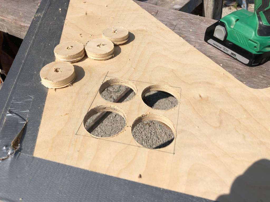
I learned a long time ago that practice makes perfect. I have made hundreds of templates and mock ups during the build of the Far Reach. I would say without fail mock ups and templates have always proved to be well worth the time and effort. Building a mock up or template reveals something that either I did not anticipate or a slightly better way to do it. There was no way I was going to cut a big hole in the cockpit well without doing it first in a piece of scrap plywood. I traced out the template that came with the control and used a hole saw to cut the holes. From that I was able to better refine the amount of fiberglass I actually needed to cut to install the control unit.

Installing the unit was not difficult. But I needed two control cables: one for the throttle linkage and one for the shifter linkage. With the shifter installed I was able to measure the length of the cables I needed. Tim Lackey gave me valuable guidance about measuring. This is one of those things where having the controller a little further away from the engine allows you space to maintain gentle radius curves for smooth throttle moving and shifting. With some basic measurement on hand I went over to the Jarrett Bay Consignment shop. Tons of stuff and most of it in very good shape. However it’s almost all big sport fishing boat stuff though somethings cross over to sailing. But, they happen to have identical 8′ control cables that fit my shifter exactly. And though they were ten years old they were still in the box. Perfect. $20 each. Home run. I took them back to the boat and installed them temporarily. They fit like a glove. Lucky me.
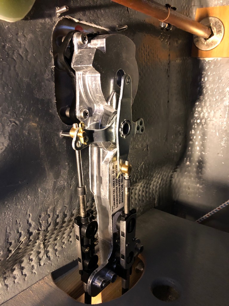
It took most of a day to hook the cables to the controller and clamp everything in place. I had a little trouble with the throttle cable…getting it adjusted properly. Turns out the threaded toggle on the engine was not fully threaded. It was a little boogered up (though brand new). It was Saturday and Beta Marine was closed. So, I bought a metric tap and chased out the threads and that solved the problem. There is some going back and forth adjustments required (adjustments on the shifter and engine end of the cables) so that the throttle lever advances all the way and its movement is matched to the throttle lever on the engine. Same for the shifter. And, I may need to adjust it some more once we get the boat in the water and use the engine a bit.
While all this was going on I was thinking about the battery charger. With the boat under cover I couldn’t use the solar panel. I had not charged the batteries since I bought them about a month or so earlier. I needed a charger. I had been reading for weeks about battery chargers. I did not enjoy reading about charges. Very ambiguous info and too many opinions. Too many different kinds of chargers. All the different battery manufactures have different charging parameters they recommend for their batteries. Trojan does not even recommend a specific charger. They simple state the charger need to charge at 14.7 volts and then be able to equalize at something like 15.3 volts. It was aggravating.
I called Odyssey Batteries who makes the AGM batteries we want to install in our Jeep Wrangler JLUR. They make a very nice portable 20 aH charger. Why can’t we get a charger that charges AGMs and the deep cycle Trojans? I left a message and the tech rep at Oddysey called me back. Turns out SHE worked for Trojan for 13 years. I learned more in 10 min from her than I had in 10 hours of reading on-line. Also, turns out the Odyssey Charger will charge to 14.7v which is exactly what Trojan wants. But the Odyssey charger does not have the higher voltage required for equalizing the Trojans. BUT…the technician said I would probably not need to equalize them unless I routinely deeply discharge them or if the battery had a cell out of whack. Baring a major problem I don’t see me discharging them much at all. And I won’t carry a charger with me offshore or out voyaging anyway. So that was a very interesting and helpful conversation. I bought the Odyssey charger. It arrived in a few days and I charged the Trojans overnight. Bulk charge at 14.7 then a slow low amp float charge at 14.3 I think.
Finally, it was time to start the engine. I installed a squeeze bulb between the fuel tank and the Racor 500 filter. This is not universally accepted as sound modification to the fuel system. Some people argue the bulb can be permeable and introduce air into the diesel fuel system which will cause the engine to fail to start or to stop running. But many other people argue it is a simple and proven modification that makes priming the engine a simple affair. It seemed so much simpler than adding an electric fuel pump which is just another thing to go wrong. Keep it simple. I added oil to the engine–Rotella– and 50:50 coolant. I checked the tranny fluid. It was full. I added five gallons of diesel to the tank and made a mark on the sounding stick. I primed the fuel filter by pouring in fuel. I worked the squeeze bulb and the lift pump but no fuel arrived at the bleed valve. I spent several hours working on it. I could not get fuel to flow from the tank down the fuel line. I went home.
Next day, I went back to the boat and took pictures of my set up and sent them to Tim Lackey. While I was waiting to hear back from him I started working backward from the fuel filter. I tested the squeeze bulb. I removed the Groco fuel valve near the tank and test it. All good. But, then I received an email from Tim who suggested I remove the first of the two ball valves (the one closest to the tank). I by-passed it and and as soon as I squeezed the bulb fuel flowed right into the Racor. So, I took that valve out of the system, though I still have a ball valve before the Racor filter. Anyway, I primed the engine and bled the air out of the system. I filled up a bucket of water below the engine and removed the raw water hose from the seacock and put the end into the bucket. I kept the charged hose in the bucket to keep it full. I made sure the exhaust seacock was open. I turned the key and listened to the buzzer. Then turned the key to start and the engine fire right up. Instantly. The idle dropped off for a few seconds and I climbed up to the cockpit and throttled up a small amount. I ran the engine for five minutes and then shut it down to check the oil and coolant levels. All good. I fired the engine back up and let it run for 20 minutes. It was a big event to actually start the engine after all the work over the past 14 months. I felt great.
With the engine start up completed I turned my attention to the propeller. Flex O Fold told me if the prop is not the right pitch they will exchange it at no cost until we get it right. The catch is it can’t be painted or in the water more than eight days. So, even though it’s a good idea to have a propeller puller now it was imperative that I be able to get the prop off with the boat in the water. To do that I took the propeller into my shop at home and with some scrap G10 and some epoxy I made a simple propeller puller that I can carry on the boat and use underwater if necessary.

The next step was to fill the fuel tank with diesel. I shuttled a five gallon container of fuel back and forth from the fuel dock to the boat and marked the sounding stick each time I added fuel. A simple fuel gauge. It won’t lie and it can’t fail.
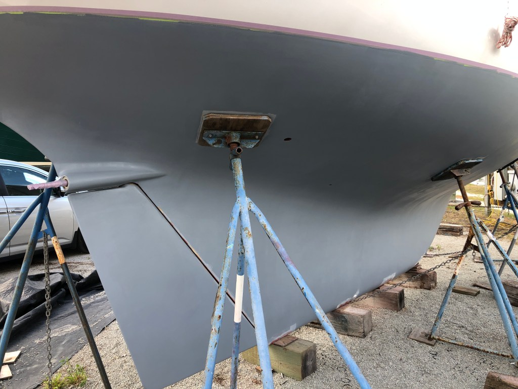
I needed to strip all the old bottom paint in preparation for painting the bottom with new barrier coat and anti fouling paint. I spent a total of about 20 hours stripping the old paint. I found the best way to strip the paint, short of paying someone about $3000 to soda blast it, was to use a pull scrapper with a double sided carbide blade. It took about 10 hours to scrape the paint off the entire hull. It was not difficult per se. By that, I mean it was not exhausting. The scraper is not heavy like trying to hold a sander against the hull. It’s a simple pulling motion and takes a while but with sharp blades does not take a lot of energy. After scraping most of the paint off I then sanding what was left which took off maybe half the barrier coat. The sanding took another 10 hours and nearly (100) 60 grit discs on my Porter Cable Double Action Random Orbital sander. So, a total of 20 hours. I used the vacuum hose and ran it into a small cyclone that is connected between the sander and the vacuum. I wore a simple pair of coveralls, knee pads, gloves, a N95 respirator, and ear plugs. I timed the weather perfectly. Most days it was about 55 to 60º F.


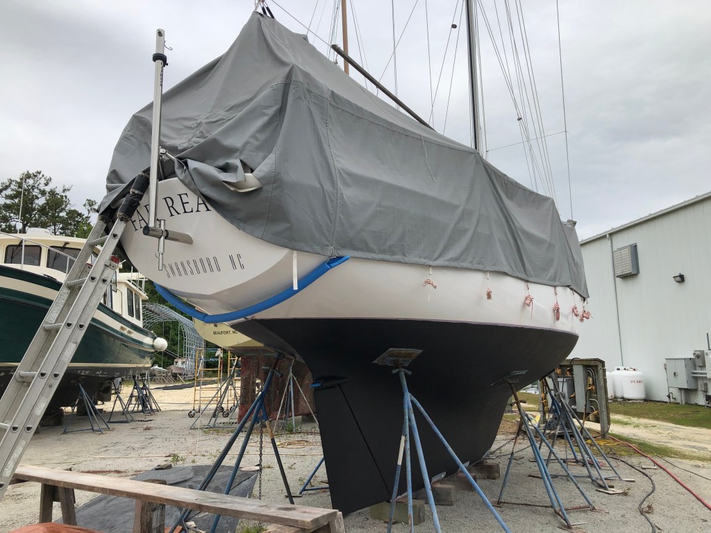
After I completed the engine installation and stripped the hull of old paint we removed the boat cover. It was great to see the boat again. We rigged up a hose and with soap and water washed the hull.

With the boat washed I rigged up my climbing harness and ascenders. Gayle belayed me with a safety line. I checked the rig over carefully. Once at the top I hauled up a garden hose on a separate halyard and with a bucket of water proceeded to wash the mast and rigging from top to bottom. Gayle took some great pictures.

After washing the boat down we put the cover back on so we could varnish the coamings. We applied three coats. One coat per day (Epiphanes High Gloss) and sand between coats. There are no short cuts with varnish regardless what some people might tell you. Well, if you are trying to achieve varnish to a high standard there are no short cuts. That’s not to say a high quality finish is the only desirable outcome. Absolutely not. It’s whatever you are trying to achieve and are willing to maintain. But if you want a high quality finish for your brightwork then you have to do the “work”. Putting the cover back on the boat eliminated most of the worry about rain, dew, dust, etc. We had to rig up shop lights though because you need a lot of light to see what you are doing. For me the goal of bright work is to look good but also to protect the wood.
In the photo below you can make out the damaged areas on the coaming I repaired three years ago. I did not want to commit to a major bright work project in the fall of 2018. We had just been clobbered by Hurricane Florence in Sept 2018. Our marina was devastated. We had five boats sunk. The roof on our house was severely damaged and had to be replaced. All of eastern NC was smashed. So, I did not have much time before I headed back to the Virgin Islands in Nov 2018. My goal was just to protect the wood. I sanded the varnish back over some breaks in the varnish and bleached the bare spots then applied 6-7 coats feathering it in. They are still holding up well. I’ll get another season in the Caribbean then probably strip it back to bare wood. It’s a lot of work. There is that word again….
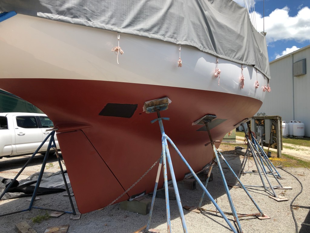
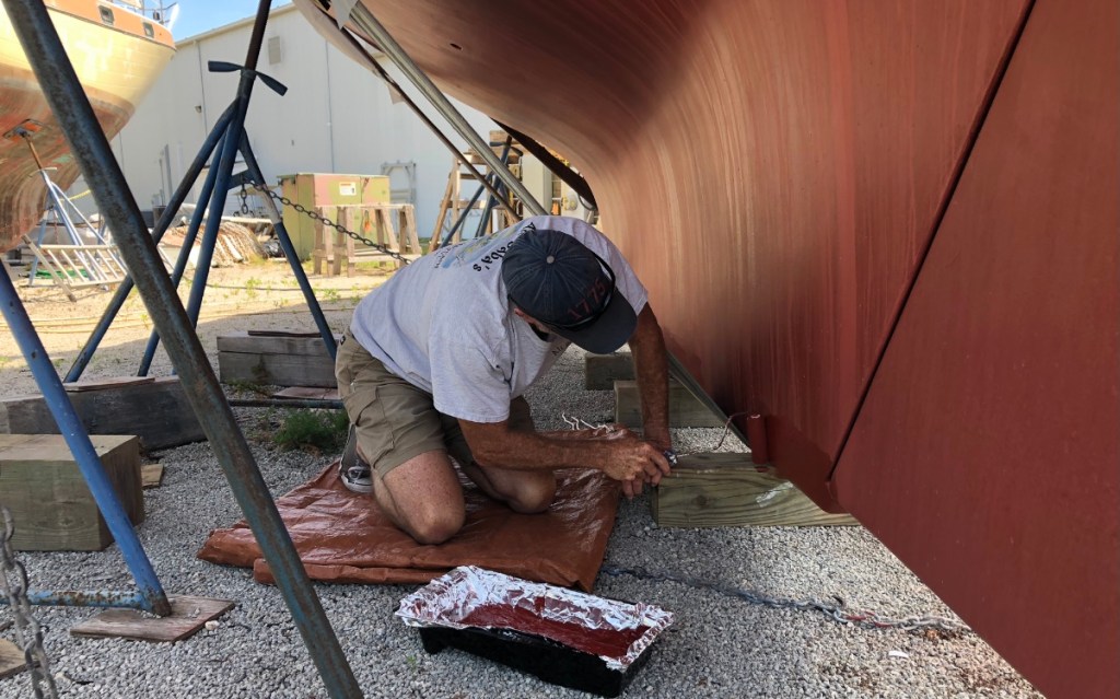
With the varnish complete it was time to barrier coat and paint the bottom. Not a lot to say about it. Pretty straight forward. Since it had been a few weeks since I scraped and sanding off the old paint I washed the hull off then ran a RO back over the hull with 80 grit. I swept it off then wiped it down with a damp cloth. Once it was dry I applied four coats of Interlux 2000e Barrier-Kote over two days. Then, with the last coat still tacky I applied a single coat of black Interlux Micron CSC anti fouling paint. The black coat serves as a “tell” when we have worked through the red paint. It’s then time to haul and apply more paint.
I let the black paint dry over night then applied a coat of red. Another day to dry and the final red coat. But we still had to move jack stands and repeat. We used white Whizz foam hot dog rollers. It took a gallon per coat of paint. While the days marched by applying barrier coat and paint I was working on other small projects.
I removed all the ash ceiling in the forward cabin (a funny name as it lines the hull not the overhead) took it home, sanded it and applied two coats of Epifanes varnish. Then we reinstalled it. In the picture to the right below you can see the insulation between the hull and the ash ceiling–two layers of Reflectix with 1/4″ blue board all taped together as a sandwich with another layer of blue board on top. One inch of insulation. This run pretty much around the entire boat from deck edge to the the cabin sole. The deck has a balsa core (to which we added 1/2″ of AP Armaflex close cell foam during the 2009-2015 rebuild) and then the overhead paneling. The Far Reach is very well insulated and it makes a big difference not only for temperature stability but also sound proofing when sailing, especially offshore.

Finally, I installed the FlexOFold two blade propeller after applying some grease to the shaft. I installed the zinc (no grease there). Then we removed the cover for the last time and stowed it at home. I cleaned the boat inside from bow to stern, vacuuming and wiping it down. It was great to have light and air pouring through open hatches and port lights. I washed the boat with Awl-Wash one more time and applied two coats of Awl-Care sealant for the paint. Our long project was just about to come to and end.
In preparation for launch we got the boat in slings so I could apply anti fouling where she had sat on keel blocks. I also applied a couple coats of varnish to the bowsprit. We tested the new LED nav lights.

I spent a couple days cleaning the boat up from the 20 plus months of work. I bent on the mainsail and hauled running rigging and blocks, life jackets, flares, dock lines, fenders and all the other equipment we need onboard to sail her.
Once we get to the marina slip I’ll pull the water tanks out of the bilge, which takes about an hour, and wash down the inside. I am pleased with how the project turned out. I am looking forward to seeing how she does under power. My hope is adding the inboard has not altered her character or lessened the wonderful magic she shares with me in the “thin spaces” that I experience when we sail together.

Let’s get going….

We are scheduled for launch in about a week.

Beautiful job,John
Shelly Tumbleson stumbleson79@gmail.com
>
LikeLike
Thanks Shelly
LikeLike
What? No forward weapons mount!? Smile. Impressive John.
LikeLike
Excellent work. Thank you for sharing. Wishing you fair winds.
LikeLike
Are you concerned about the lack of water flow to lubricate the cutless bearing? Did I just miss a small hole from the outside to the prop shaft forward of the cutless bearing.
LikeLike
Hi Redhak. I just saw this so sorry about the delay. Short answer: no issues. Longer answer: There are grooves cut in the cutless bearing and water works up into the grooves to gain access the packing material around the stuffing box. I used gore stuffing so pretty quickly the few drips I got stopped. I checked the temperature on the stuffing box underway and made some minor adjustments till it stayed cool with no water drops.
LikeLike
Hi, John. Can’t seem to find the make of engine or HP you decided to go with. I am looking at buying a CD 36 that is a bit worse for wear and needs repowering. It currently has a Perkins Pima M50 which seems like overkill. To save weight and space I would think I could go a lot smaller since I would only be using it really to get in and out of harbor/anchorage (this is a sailing vessel, after all). I apologize if the info is somewhere in these pages and I just missed it.
Thanks – Mike
LikeLike
Hi Mike. I installed a Beta 25HP which has worked perfectly for the way I installed it. Completely satisfied. I bought it through Beta Marine USA in Minnesott Beach/Oriental NC. The are the US importer for Beta Marine Ltd. Talk to Farron Peffer.
I will share that I think most CD 36 owners would probably be happier with a Beta 35 hp.
John
LikeLike